Downloaded 740 times


This document provides an overview of assembly language for the x86 architecture. It discusses what assembly language is, why it is used, basic concepts like data sizes, and details of the x86 architecture like its modes of operation and basic program execution registers including general purpose registers, segment registers, the EFLAGS register, and status flags.
Overview of Assembly Language, its role in processor operations, and how it translates machine instructions into symbolic code.
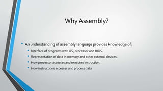
Assembly language as a low-level programming tool that helps understand OS interfacing, memory representation, and processor instruction execution.
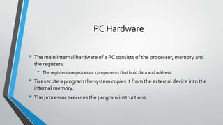
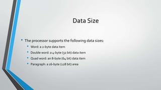
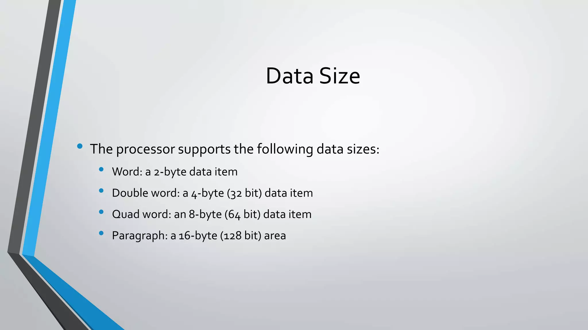
Description of the PC's internal hardware including the processor, memory, registers, and data size definitions.
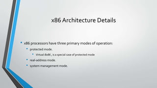
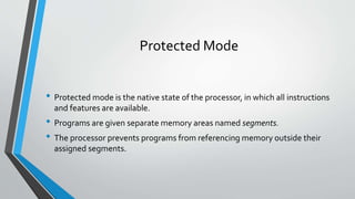
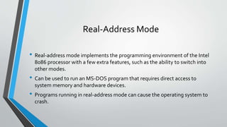
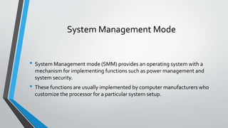
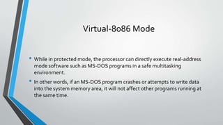
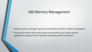
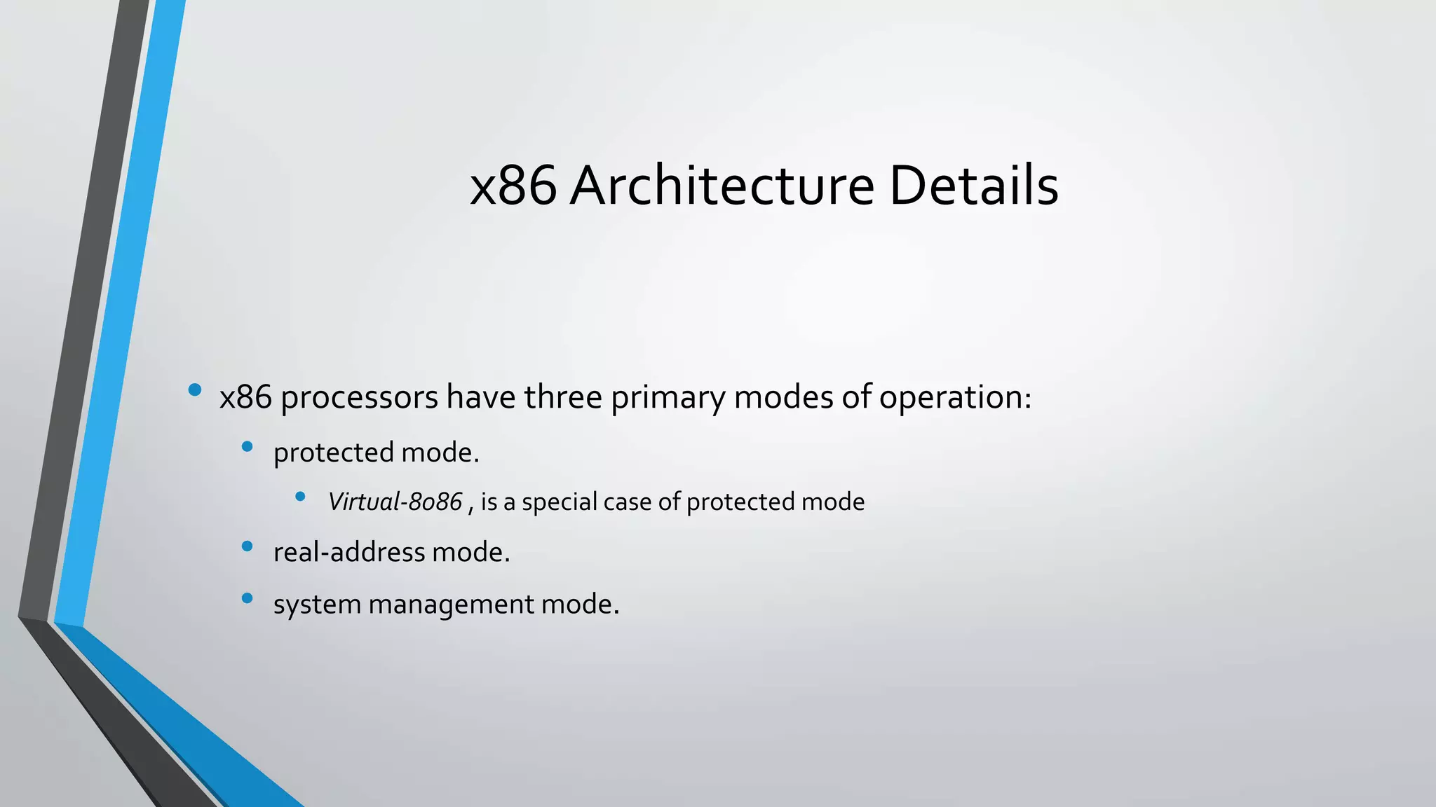
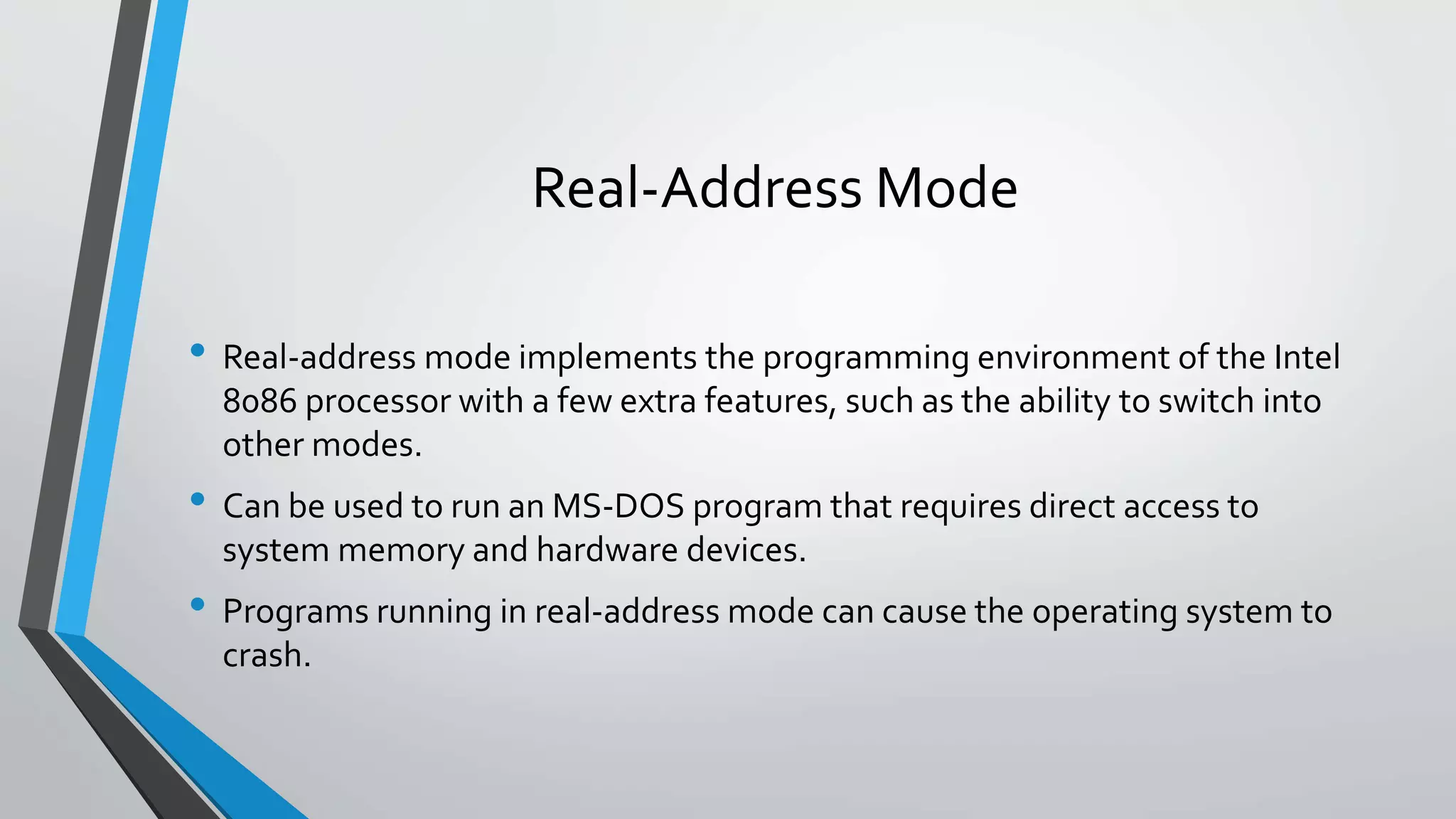
Details on x86 processor modes including Protected, Real-Address, System Management, and Virtual-8086 for executing programs.
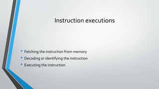
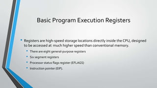
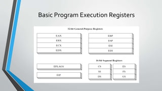
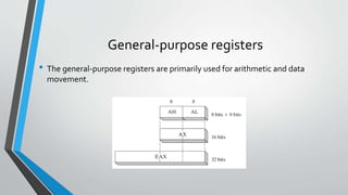
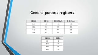
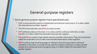
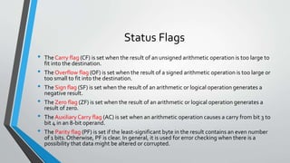
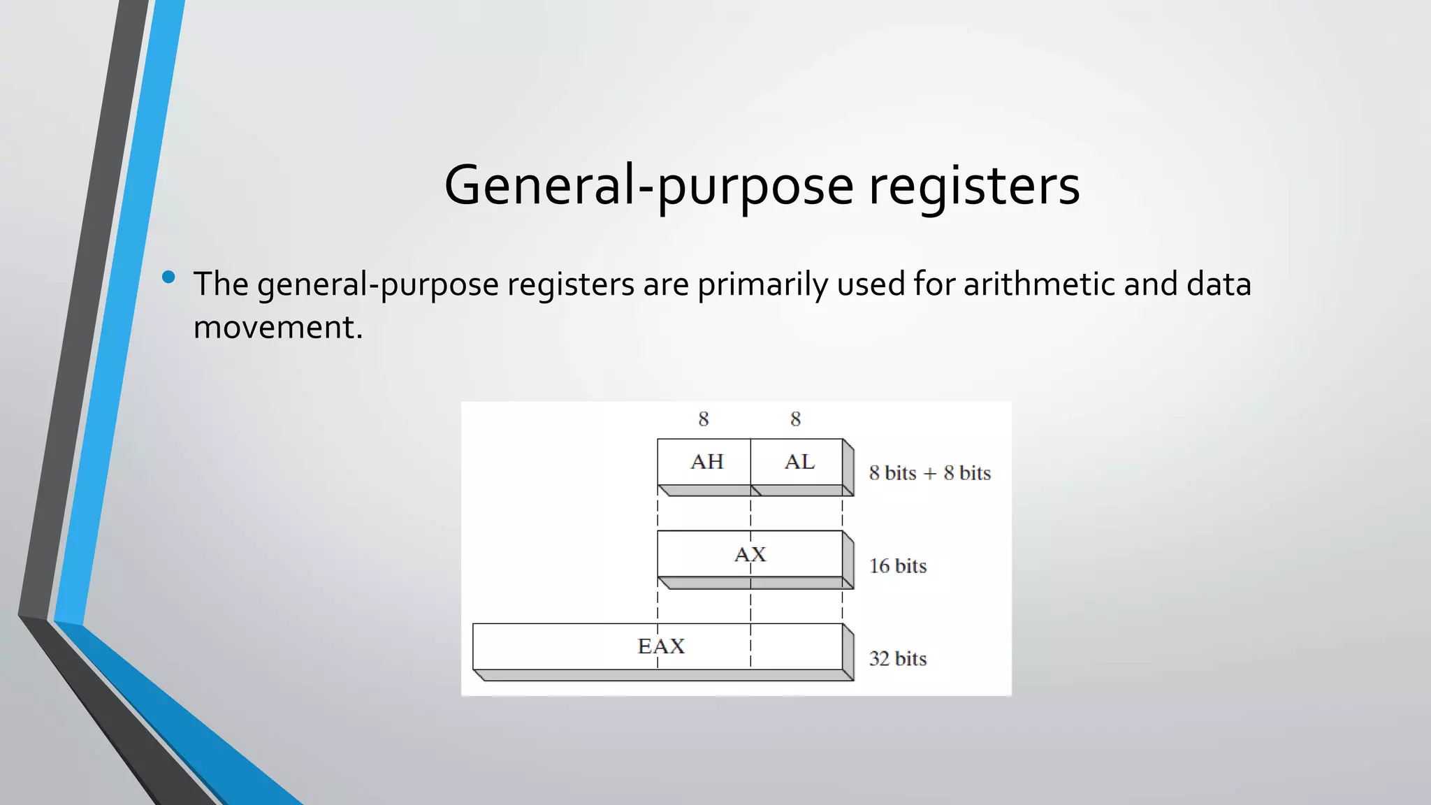
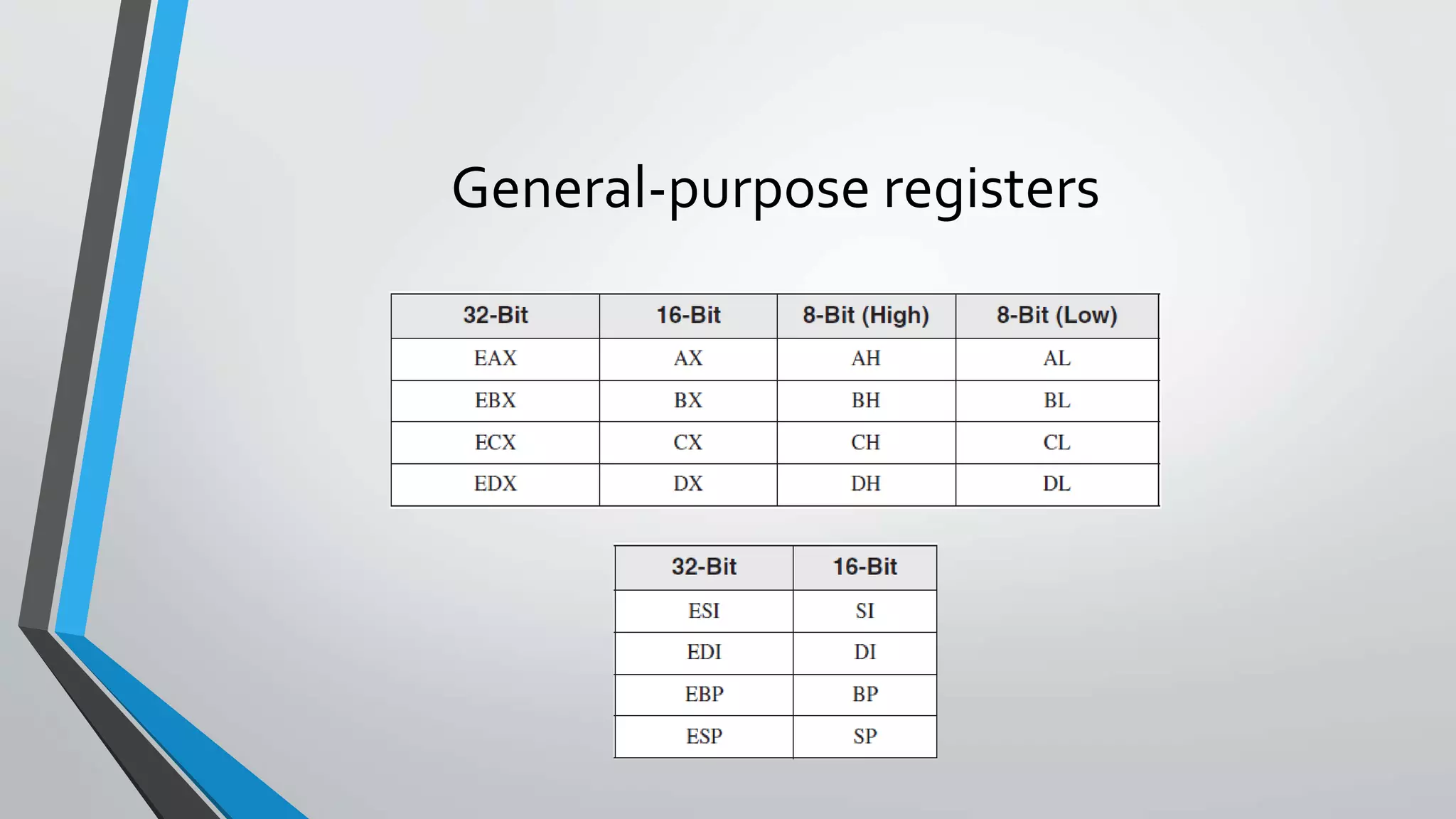
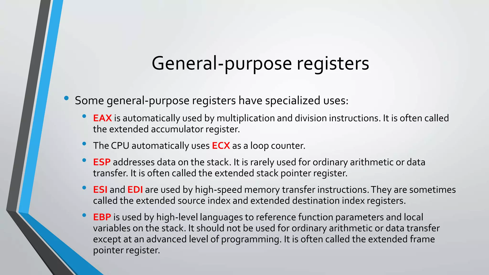
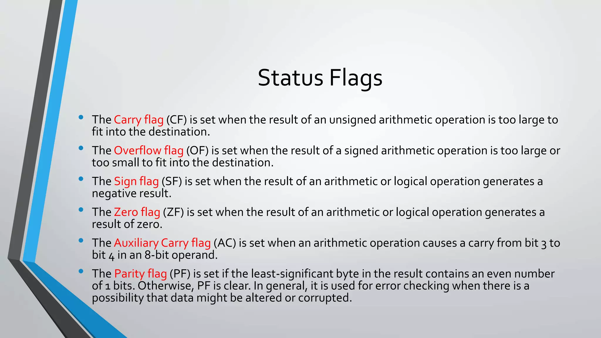
Explanation of program execution registers, their types, functions, and specific uses of general-purpose registers in assembly.
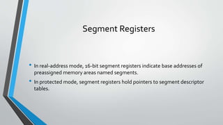
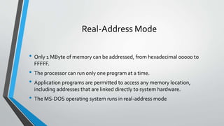
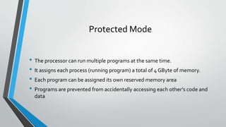
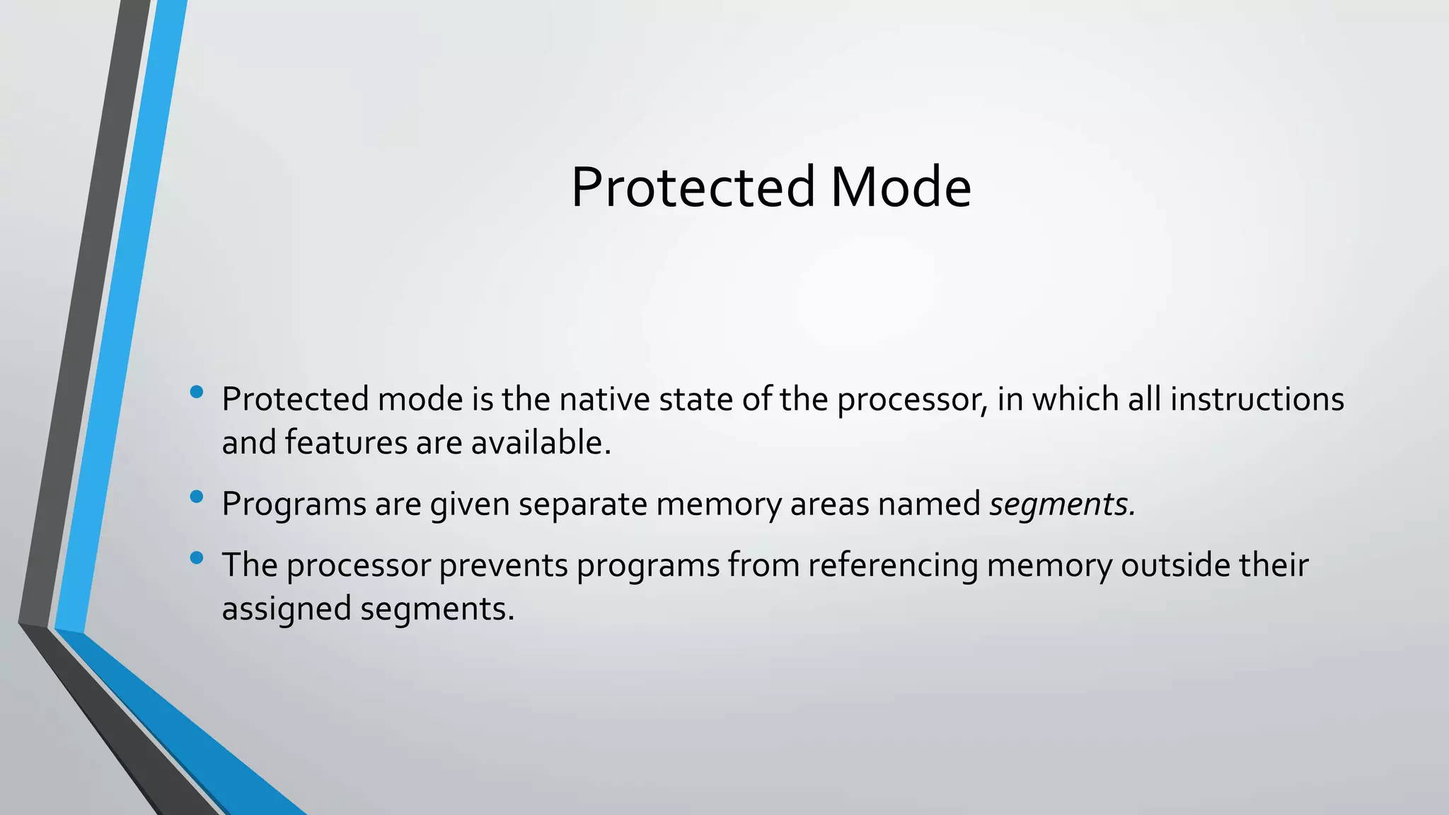
Differences in memory management between Protected and Real-Address modes, including access permissions and memory assignment.


