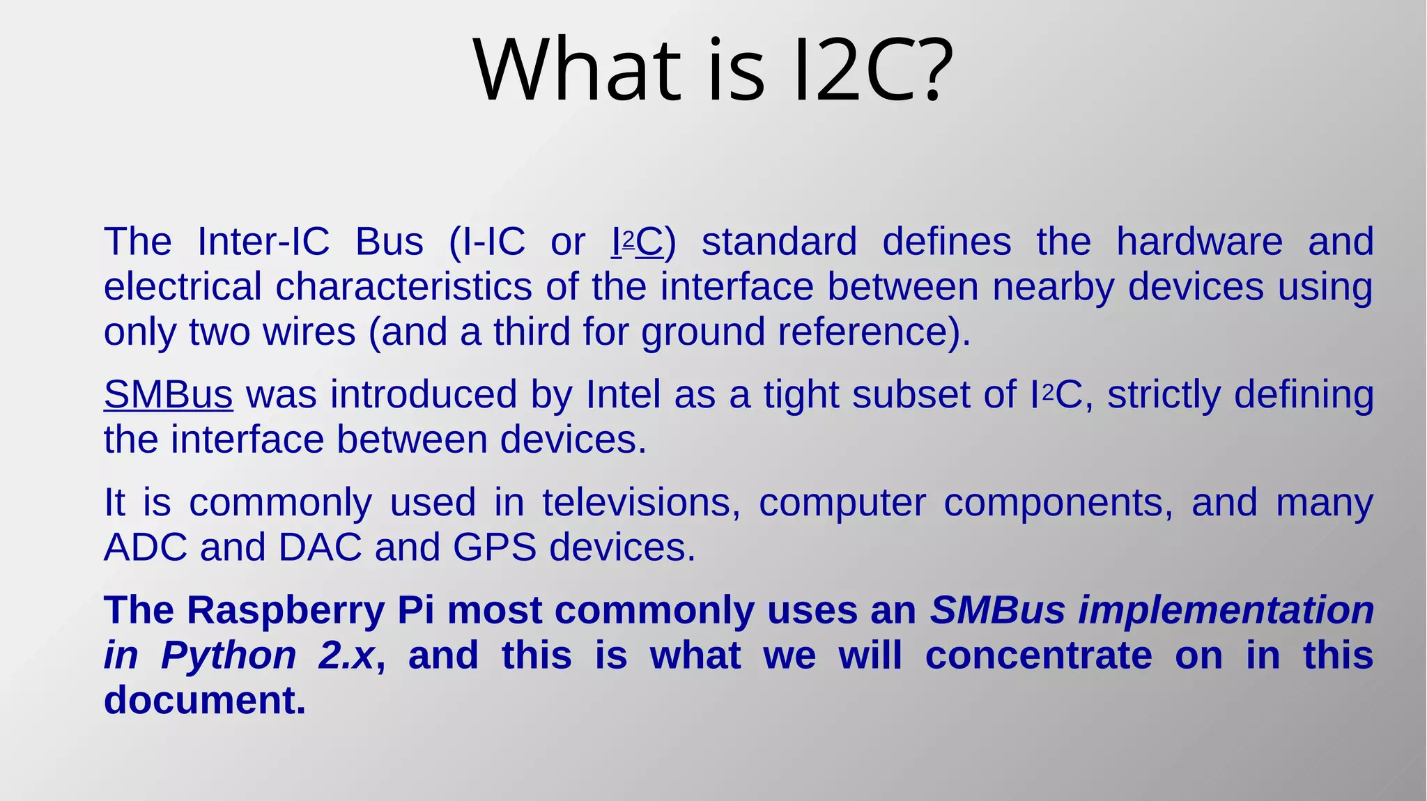
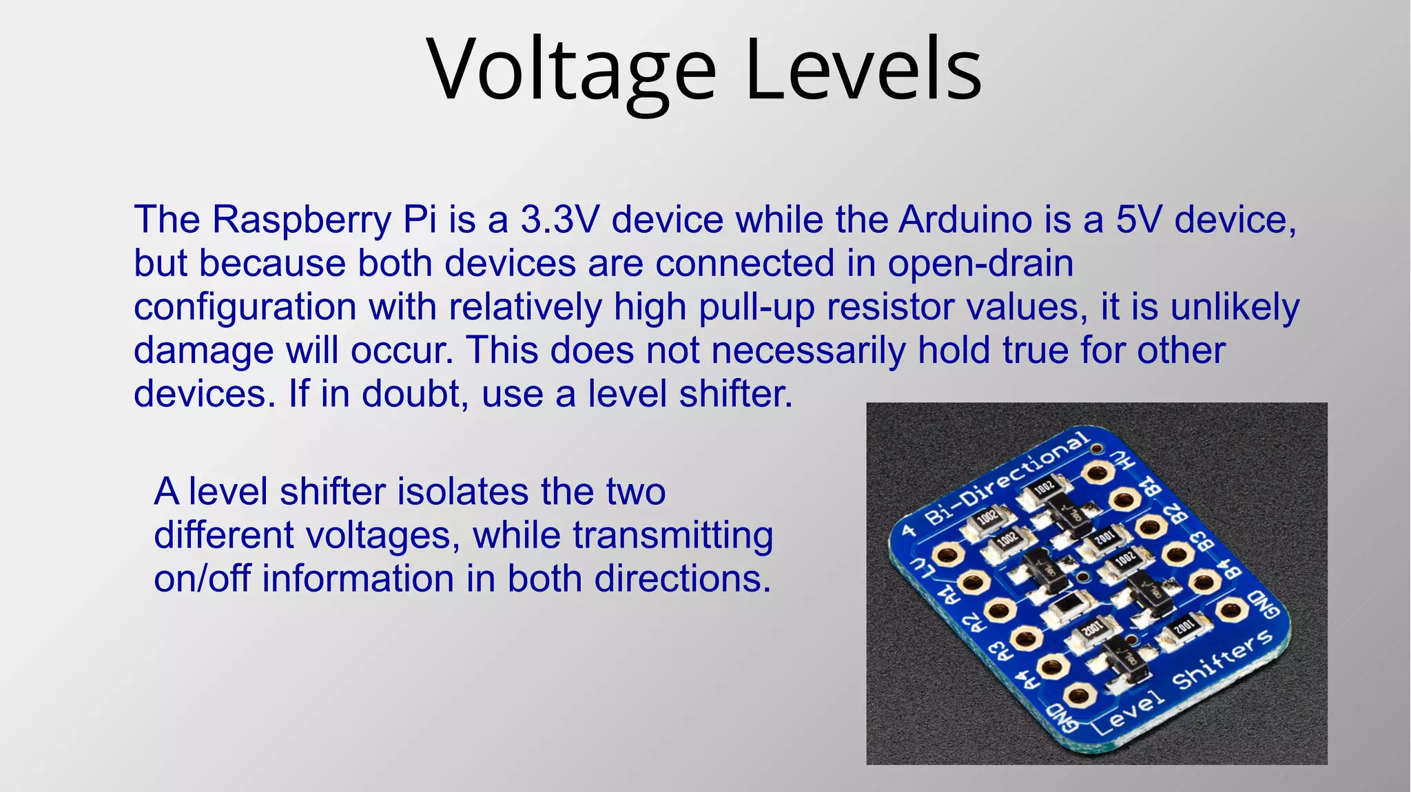
This document provides a comprehensive guide for connecting a Raspberry Pi to an Arduino using the I2C protocol, detailing the hardware setup, voltage level considerations, and software configuration in Python. It includes instructions for creating a level shifter to ensure compatibility between the Raspberry Pi's 3.3V and Arduino's 5V systems, as well as code examples for both devices. An example project is also described, where the Raspberry Pi controls an RGB LED connected to the Arduino and facilitates data exchange such as temperature and light levels.


![Preparing the Raspberry Pi
Start Python, and create a new file.
Import the SMBus library.
Create an SMBus object linked to I2C port 1.
Define the slaves address(es) to connect to.
Collect the data to be transmitted, or prepare the
data variables for reading back from the slave.
These instructions are for Python 2. Python 3 may have small differences.
import smbus
i2c_object = smbus.SMBus(1)
# Link to SMBus(0) on older Pi
addrSlave1 = 8
command = 0
dataList = [1,2,3,4,5]
i2c_object.write_i2c_block_data(addrSlave1,
command,
DataList)
getDataList = i2c_object.read_i2c_block_data(
addrSlave1,
command)](https://image.slidesharecdn.com/i2cinterfacingraspberrypitoarduino-160301170310/85/I2c-interfacing-raspberry-pi-to-arduino-9-320.jpg)


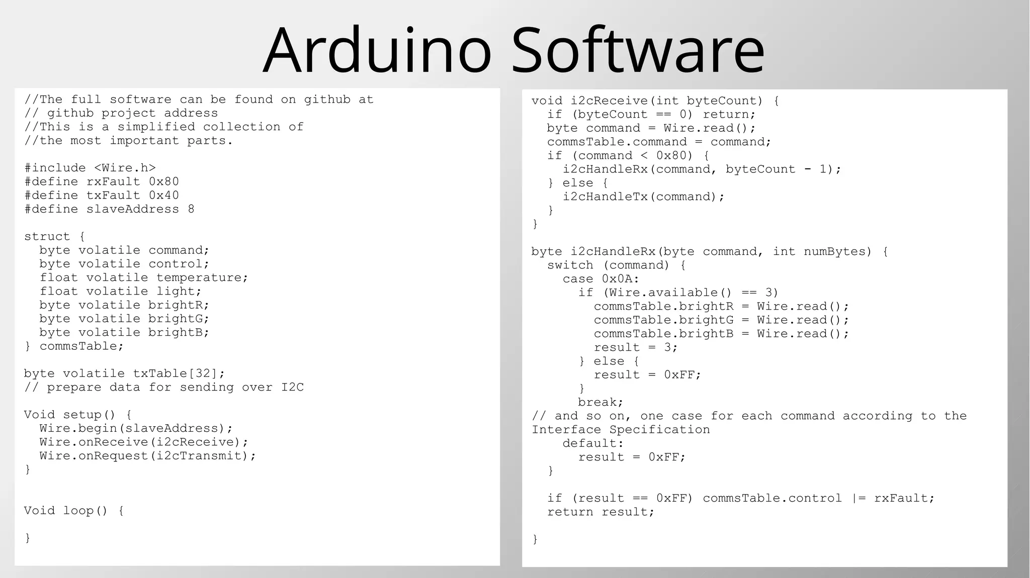
![Arduino Software//The full software can be found on github at
// https://github.com/MikeOchtman/Pi_Arduino_I2C
//This is a simplified collection of
//the most important parts.
#include <Wire.h>
#define rxFault 0x80
#define txFault 0x40
#define slaveAddress 8
struct {
byte volatile command;
byte volatile control;
float volatile temperature;
float volatile light;
byte volatile brightR;
byte volatile brightG;
byte volatile brightB;
} commsTable;
byte volatile txTable[32];
// prepare data for sending over I2C
Void setup() {
Wire.begin(slaveAddress);
Wire.onReceive(i2cReceive);
Wire.onRequest(i2cTransmit);
}
Void loop() {
}
void i2cReceive(int byteCount) {
if (byteCount == 0) return;
byte command = Wire.read();
commsTable.command = command;
if (command < 0x80) {
i2cHandleRx(command, byteCount - 1);
} else {
i2cHandleTx(command);
}
}
byte i2cHandleRx(byte command, int numBytes) {
switch (command) {
case 0x0A:
if (Wire.available() == 3)
commsTable.brightR = Wire.read();
commsTable.brightG = Wire.read();
commsTable.brightB = Wire.read();
result = 3;
} else {
result = 0xFF;
}
break;
// and so on, one case for each command according to the
Interface Specification
default:
result = 0xFF;
}
if (result == 0xFF) commsTable.control |= rxFault;
return result;
}](https://image.slidesharecdn.com/i2cinterfacingraspberrypitoarduino-160301170310/85/I2c-interfacing-raspberry-pi-to-arduino-13-320.jpg)
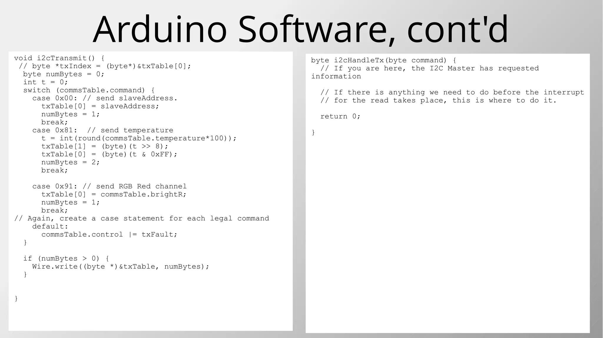
![Arduino Software, cont'd
byte i2cHandleTx(byte command) {
// If you are here, the I2C Master has requested
information
// If there is anything we need to do before the interrupt
// for the read takes place, this is where to do it.
return 0;
}
void i2cTransmit() {
// byte *txIndex = (byte*)&txTable[0];
byte numBytes = 0;
int t = 0;
switch (commsTable.command) {
case 0x00: // send slaveAddress.
txTable[0] = slaveAddress;
numBytes = 1;
break;
case 0x81: // send temperature
t = int(round(commsTable.temperature*100));
txTable[1] = (byte)(t >> 8);
txTable[0] = (byte)(t & 0xFF);
numBytes = 2;
break;
case 0x91: // send RGB Red channel
txTable[0] = commsTable.brightR;
numBytes = 1;
break;
// Again, create a case statement for each legal command
default:
commsTable.control |= txFault;
}
if (numBytes > 0) {
Wire.write((byte *)&txTable, numBytes);
}
}](https://image.slidesharecdn.com/i2cinterfacingraspberrypitoarduino-160301170310/85/I2c-interfacing-raspberry-pi-to-arduino-14-320.jpg)
![Python Softwareimport smbus
import time
i2c = smbus.SMBus(1)
addr = 8 # address of the arduino I2C
##/* Interface Specification
## Data in a table thus:
## byte purpose
## 0: command
## 1: control
## 2-5: Current Temperature (read-only)
## 6-9: Current light level (read only)
## 10: Brightness for RED r/w
## 11: Brightness for GREEN r/w
## 12: Brightness for BLUE r/w
## Commands:
## Write with no command: Ignore
## Read with no command: Return slave address
## Command 0x81: read temperature;
## Integer returned, int(round(temp*100))
## Command 0x82: read light level;
## Integer returned, int(round(lux*100))
## Command 0x0A: Write three bytes to RGB
## Command 0x0B: Write single byte brightness red;
## Command 0x0C: Write single byte brightness green;
## Command 0x0D: Write single byte brightness blue;
## Command 0x90: read three bytes brightness RGB
## Command 0x91: read single byte brightness red;
## Command 0x92: read single byte brightness green;
## Command 0x93: read single byte brightness blue;
##
## All other values are ignored, no data returned.
RGB = [20,200,128]
temperature = 0
light_level = 0
i2c.write_quick(addr) # no data expected back
time.sleep(0.5)
print i2c.read_byte(addr) # expect the slave address
time.sleep(0.5)
print i2c.read_word_data(addr,0x81)/100.0 # temperature
time.sleep(0.5)
print i2c.read_word_data(addr,0x82)/100.0 # light level
time.sleep(0.5)
i2c.write_byte_data(addr, 0x0B, 12) # write Red value
time.sleep(0.5)
print i2c.read_byte_data(addr, 0x91) # write Green value
time.sleep(0.5)
i2c.write_byte_data(addr, 0x0C, 123) # write Blue value
time.sleep(0.5)
print i2c.read_byte_data(addr, 0x92) # get Green value
time.sleep(0.5)
i2c.write_byte_data(addr, 0x0D, 234) # write Blue value
time.sleep(0.5)
print i2c.read_byte_data(addr, 0x93) # get Blue value
time.sleep(0.5)
print i2c.read_i2c_block_data(addr, 0x90, 3) # get RGB
time.sleep(0.5)
i2c.write_i2c_block_data(addr, 0x0A, RGB) # set all RGB
time.sleep(0.5)
print i2c.read_i2c_block_data(addr, 0x90, 3) # get all RGB
time.sleep(0.5)
print i2c.read_i2c_block_data(addr, 0x10, 3) # force error
time.sleep(0.5)](https://image.slidesharecdn.com/i2cinterfacingraspberrypitoarduino-160301170310/85/I2c-interfacing-raspberry-pi-to-arduino-15-320.jpg)
![The Python ResultsPython 2.7.9 results.
>>>
8
23.95
6.97
12
123
234
[12, 123, 234]
[20, 200, 128]
[0, 255, 255]
>>>
No event for write_quick()
Got back the slave Address.
Got the simulated temperature
Got the simulated light level
Set and read back Red channel
Set and read back Green channel
Set and read back Blue channel
Got back RGB values as a list.
Set new RGB values from a list
Read back the RGB values as a list
Forced a read error by sending wrong command.
RGB = [20,200,128]
i2c.write_quick(addr) # no data expected back
print i2c.read_byte(addr) # expect the slave address
print i2c.read_word_data(addr,0x81)/100.0 # temperature
print i2c.read_word_data(addr,0x82)/100.0 # light level
i2c.write_byte_data(addr, 0x0B, 12) # write Red value
print i2c.read_byte_data(addr, 0x91) # get Red value
i2c.write_byte_data(addr, 0x0C, 123) # write Green value
print i2c.read_byte_data(addr, 0x92) # get Green value
i2c.write_byte_data(addr, 0x0D, 234) # write Blue value
print i2c.read_byte_data(addr, 0x93) # get Blue value
print i2c.read_i2c_block_data(addr, 0x90, 3) # get RGB
i2c.write_i2c_block_data(addr, 0x0A, RGB) # set all RGB
print i2c.read_i2c_block_data(addr, 0x90, 3) # get all RGB
print i2c.read_i2c_block_data(addr, 0x10, 3) # force error](https://image.slidesharecdn.com/i2cinterfacingraspberrypitoarduino-160301170310/85/I2c-interfacing-raspberry-pi-to-arduino-16-320.jpg)

![Instructions in Detail
Master (Rpi, Python) Slave (Arduino
Bus.write_word_data(addr, command, integerVal)
Send slave extra information accompanying a specific command
Wire.onReceive() event triggered, three bytes send. First byte is
command, second is LSB, third is MSB of integer.
Bytes received: 3. Bytes returned: 0.
WordValue = Bus.read_word_data(addr, command)
Retrieve two bytes, first LSB, then MSB of an integer. Python knows
to rebuild the integer. Retrieve integer data from slave.
Wire.onReceive() event triggered. Single byte received, a
command. Wire.onRequest() event triggered, slave must send back
two bytes, first LSB, then MSB, of an integer.
Bytes received: 1. Bytes returned: 2.
Bus.write_block_data(addr, command, [list of bytes])
Sending unstructured data.
Wire.onReceive() event triggered. Several bytes sent. First byte is
command, second is number of following bytes, remainder of bytes
must be processes according to interface list.
Bytes received: > 2. Bytes returned: 0.
Bus.write_i2c_block_data(addr, command, [list of bytes])
Use this to fill a table of related bytes quickly.
Wire.onReceive() event triggered. Several bytes sent. First byte is a
command, remaining bytes to be processed according to interface.
Bytes received: > 1. Bytes returned: 0.
ByteList = Bus.read_i2c_block_data(addr, command)
Use this to read a table of related bytes quickly
Wire.onReceive event triggered. One byte sent, a command for
which byte is requested from slave. Wire.onRequest() then
triggered, requested bytes returned as per interface list.
Bytes received: 1. Bytes returned: > 1](https://image.slidesharecdn.com/i2cinterfacingraspberrypitoarduino-160301170310/85/I2c-interfacing-raspberry-pi-to-arduino-18-320.jpg)
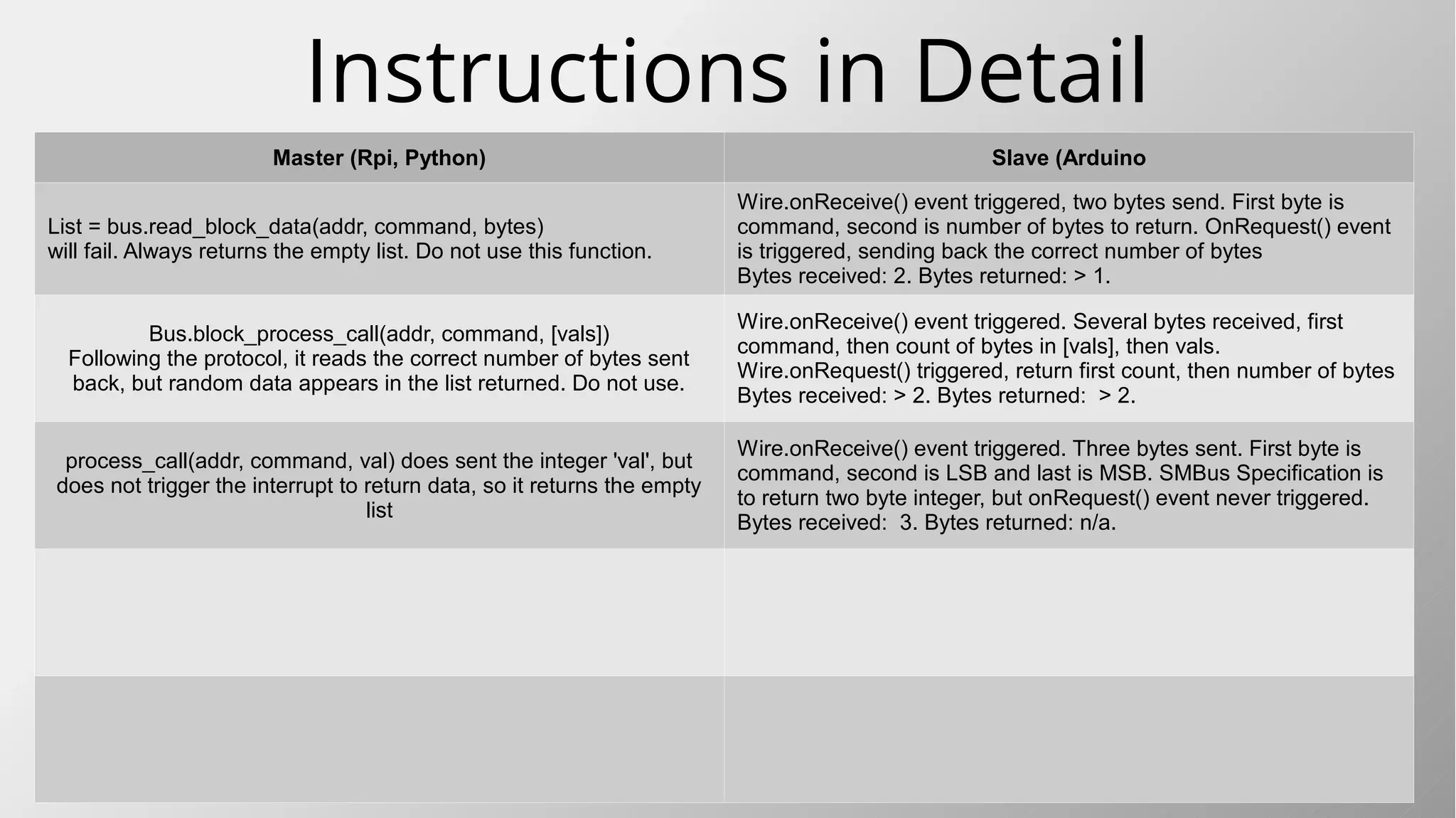
![Instructions in Detail
Master (Rpi, Python) Slave (Arduino
List = bus.read_block_data(addr, command, bytes)
will fail. Always returns the empty list. Do not use this function.
Wire.onReceive() event triggered, two bytes send. First byte is
command, second is number of bytes to return. OnRequest() event
is triggered, sending back the correct number of bytes
Bytes received: 2. Bytes returned: > 1.
Bus.block_process_call(addr, command, [vals])
Following the protocol, it reads the correct number of bytes sent
back, but random data appears in the list returned. Do not use.
Wire.onReceive() event triggered. Several bytes received, first
command, then count of bytes in [vals], then vals.
Wire.onRequest() triggered, return first count, then number of bytes
Bytes received: > 2. Bytes returned: > 2.
process_call(addr, command, val) does sent the integer 'val', but
does not trigger the interrupt to return data, so it returns the empty
list
Wire.onReceive() event triggered. Three bytes sent. First byte is
command, second is LSB and last is MSB. SMBus Specification is
to return two byte integer, but onRequest() event never triggered.
Bytes received: 3. Bytes returned: n/a.](https://image.slidesharecdn.com/i2cinterfacingraspberrypitoarduino-160301170310/85/I2c-interfacing-raspberry-pi-to-arduino-19-320.jpg)
![Conclusions
Communication over I2C is quite simple to
implement using the SMBus library on the
Raspberry Pi, and the Wire.h library on the
Arduino..
Knowing what each SMBus Write and Read
instruction sends to the Arduino and what data
the Arduino is expected to send back is crucial
to successful implementation of the I2C/SMBus
protocol.
Before coding, have a clear Interface
Specification with a list of commands to be sent
to the Arduino, and clear instructions of what
should happen with the data sent and how to
return requested data.
It is also important to specify the reaction to
bad data.
The SMBus protocol document can be found at
http://smbus.org/specs/smbus20.pdf
The linux Python implementation document can be
found at
https://www.kernel.org/doc/Documentation/i2c/smb
us-protocol
Some of the SMBus protocol is not fully
programmed in the existing SMBus python
libraries, even though the functions are
available to include in the program.
These functions do not appear to work with the
arduino:
● read_block_data(addr, command, bytes)
● block_process_call(addr, command, [vals])
● process_call(addr, command, val)
All the other functions appear to operate
according to the specification.
This work is licensed under the
Creative Commons Attribution-
ShareAlike 4.0 International License.
To view a copy of this license, visit
http://creativecommons.org/licenses/b
y-sa/4.0/.
Compiled by Mike Ochtman.
Find me at
https://za.linkedin.com/in/mikeochtman](https://image.slidesharecdn.com/i2cinterfacingraspberrypitoarduino-160301170310/85/I2c-interfacing-raspberry-pi-to-arduino-20-320.jpg)


![Preparing the Raspberry Pi
Start Python, and create a new file.
Import the SMBus library.
Create an SMBus object linked to I2C port 1.
Define the slaves address(es) to connect to.
Collect the data to be transmitted, or prepare the
data variables for reading back from the slave.
These instructions are for Python 2. Python 3 may have small differences.
import smbus
i2c_object = smbus.SMBus(1)
# Link to SMBus(0) on older Pi
addrSlave1 = 8
command = 0
dataList = [1,2,3,4,5]
i2c_object.write_i2c_block_data(addrSlave1,
command,
DataList)
getDataList = i2c_object.read_i2c_block_data(
addrSlave1,
command)](https://image.slidesharecdn.com/i2cinterfacingraspberrypitoarduino-160301170310/75/I2c-interfacing-raspberry-pi-to-arduino-9-2048.jpg)
![Arduino Software//The full software can be found on github at
// https://github.com/MikeOchtman/Pi_Arduino_I2C
//This is a simplified collection of
//the most important parts.
#include <Wire.h>
#define rxFault 0x80
#define txFault 0x40
#define slaveAddress 8
struct {
byte volatile command;
byte volatile control;
float volatile temperature;
float volatile light;
byte volatile brightR;
byte volatile brightG;
byte volatile brightB;
} commsTable;
byte volatile txTable[32];
// prepare data for sending over I2C
Void setup() {
Wire.begin(slaveAddress);
Wire.onReceive(i2cReceive);
Wire.onRequest(i2cTransmit);
}
Void loop() {
}
void i2cReceive(int byteCount) {
if (byteCount == 0) return;
byte command = Wire.read();
commsTable.command = command;
if (command < 0x80) {
i2cHandleRx(command, byteCount - 1);
} else {
i2cHandleTx(command);
}
}
byte i2cHandleRx(byte command, int numBytes) {
switch (command) {
case 0x0A:
if (Wire.available() == 3)
commsTable.brightR = Wire.read();
commsTable.brightG = Wire.read();
commsTable.brightB = Wire.read();
result = 3;
} else {
result = 0xFF;
}
break;
// and so on, one case for each command according to the
Interface Specification
default:
result = 0xFF;
}
if (result == 0xFF) commsTable.control |= rxFault;
return result;
}](https://image.slidesharecdn.com/i2cinterfacingraspberrypitoarduino-160301170310/75/I2c-interfacing-raspberry-pi-to-arduino-13-2048.jpg)
![Arduino Software, cont'd
byte i2cHandleTx(byte command) {
// If you are here, the I2C Master has requested
information
// If there is anything we need to do before the interrupt
// for the read takes place, this is where to do it.
return 0;
}
void i2cTransmit() {
// byte *txIndex = (byte*)&txTable[0];
byte numBytes = 0;
int t = 0;
switch (commsTable.command) {
case 0x00: // send slaveAddress.
txTable[0] = slaveAddress;
numBytes = 1;
break;
case 0x81: // send temperature
t = int(round(commsTable.temperature*100));
txTable[1] = (byte)(t >> 8);
txTable[0] = (byte)(t & 0xFF);
numBytes = 2;
break;
case 0x91: // send RGB Red channel
txTable[0] = commsTable.brightR;
numBytes = 1;
break;
// Again, create a case statement for each legal command
default:
commsTable.control |= txFault;
}
if (numBytes > 0) {
Wire.write((byte *)&txTable, numBytes);
}
}](https://image.slidesharecdn.com/i2cinterfacingraspberrypitoarduino-160301170310/75/I2c-interfacing-raspberry-pi-to-arduino-14-2048.jpg)
![Python Softwareimport smbus
import time
i2c = smbus.SMBus(1)
addr = 8 # address of the arduino I2C
##/* Interface Specification
## Data in a table thus:
## byte purpose
## 0: command
## 1: control
## 2-5: Current Temperature (read-only)
## 6-9: Current light level (read only)
## 10: Brightness for RED r/w
## 11: Brightness for GREEN r/w
## 12: Brightness for BLUE r/w
## Commands:
## Write with no command: Ignore
## Read with no command: Return slave address
## Command 0x81: read temperature;
## Integer returned, int(round(temp*100))
## Command 0x82: read light level;
## Integer returned, int(round(lux*100))
## Command 0x0A: Write three bytes to RGB
## Command 0x0B: Write single byte brightness red;
## Command 0x0C: Write single byte brightness green;
## Command 0x0D: Write single byte brightness blue;
## Command 0x90: read three bytes brightness RGB
## Command 0x91: read single byte brightness red;
## Command 0x92: read single byte brightness green;
## Command 0x93: read single byte brightness blue;
##
## All other values are ignored, no data returned.
RGB = [20,200,128]
temperature = 0
light_level = 0
i2c.write_quick(addr) # no data expected back
time.sleep(0.5)
print i2c.read_byte(addr) # expect the slave address
time.sleep(0.5)
print i2c.read_word_data(addr,0x81)/100.0 # temperature
time.sleep(0.5)
print i2c.read_word_data(addr,0x82)/100.0 # light level
time.sleep(0.5)
i2c.write_byte_data(addr, 0x0B, 12) # write Red value
time.sleep(0.5)
print i2c.read_byte_data(addr, 0x91) # write Green value
time.sleep(0.5)
i2c.write_byte_data(addr, 0x0C, 123) # write Blue value
time.sleep(0.5)
print i2c.read_byte_data(addr, 0x92) # get Green value
time.sleep(0.5)
i2c.write_byte_data(addr, 0x0D, 234) # write Blue value
time.sleep(0.5)
print i2c.read_byte_data(addr, 0x93) # get Blue value
time.sleep(0.5)
print i2c.read_i2c_block_data(addr, 0x90, 3) # get RGB
time.sleep(0.5)
i2c.write_i2c_block_data(addr, 0x0A, RGB) # set all RGB
time.sleep(0.5)
print i2c.read_i2c_block_data(addr, 0x90, 3) # get all RGB
time.sleep(0.5)
print i2c.read_i2c_block_data(addr, 0x10, 3) # force error
time.sleep(0.5)](https://image.slidesharecdn.com/i2cinterfacingraspberrypitoarduino-160301170310/75/I2c-interfacing-raspberry-pi-to-arduino-15-2048.jpg)
![The Python ResultsPython 2.7.9 results.
>>>
8
23.95
6.97
12
123
234
[12, 123, 234]
[20, 200, 128]
[0, 255, 255]
>>>
No event for write_quick()
Got back the slave Address.
Got the simulated temperature
Got the simulated light level
Set and read back Red channel
Set and read back Green channel
Set and read back Blue channel
Got back RGB values as a list.
Set new RGB values from a list
Read back the RGB values as a list
Forced a read error by sending wrong command.
RGB = [20,200,128]
i2c.write_quick(addr) # no data expected back
print i2c.read_byte(addr) # expect the slave address
print i2c.read_word_data(addr,0x81)/100.0 # temperature
print i2c.read_word_data(addr,0x82)/100.0 # light level
i2c.write_byte_data(addr, 0x0B, 12) # write Red value
print i2c.read_byte_data(addr, 0x91) # get Red value
i2c.write_byte_data(addr, 0x0C, 123) # write Green value
print i2c.read_byte_data(addr, 0x92) # get Green value
i2c.write_byte_data(addr, 0x0D, 234) # write Blue value
print i2c.read_byte_data(addr, 0x93) # get Blue value
print i2c.read_i2c_block_data(addr, 0x90, 3) # get RGB
i2c.write_i2c_block_data(addr, 0x0A, RGB) # set all RGB
print i2c.read_i2c_block_data(addr, 0x90, 3) # get all RGB
print i2c.read_i2c_block_data(addr, 0x10, 3) # force error](https://image.slidesharecdn.com/i2cinterfacingraspberrypitoarduino-160301170310/75/I2c-interfacing-raspberry-pi-to-arduino-16-2048.jpg)
![Instructions in Detail
Master (Rpi, Python) Slave (Arduino
Bus.write_word_data(addr, command, integerVal)
Send slave extra information accompanying a specific command
Wire.onReceive() event triggered, three bytes send. First byte is
command, second is LSB, third is MSB of integer.
Bytes received: 3. Bytes returned: 0.
WordValue = Bus.read_word_data(addr, command)
Retrieve two bytes, first LSB, then MSB of an integer. Python knows
to rebuild the integer. Retrieve integer data from slave.
Wire.onReceive() event triggered. Single byte received, a
command. Wire.onRequest() event triggered, slave must send back
two bytes, first LSB, then MSB, of an integer.
Bytes received: 1. Bytes returned: 2.
Bus.write_block_data(addr, command, [list of bytes])
Sending unstructured data.
Wire.onReceive() event triggered. Several bytes sent. First byte is
command, second is number of following bytes, remainder of bytes
must be processes according to interface list.
Bytes received: > 2. Bytes returned: 0.
Bus.write_i2c_block_data(addr, command, [list of bytes])
Use this to fill a table of related bytes quickly.
Wire.onReceive() event triggered. Several bytes sent. First byte is a
command, remaining bytes to be processed according to interface.
Bytes received: > 1. Bytes returned: 0.
ByteList = Bus.read_i2c_block_data(addr, command)
Use this to read a table of related bytes quickly
Wire.onReceive event triggered. One byte sent, a command for
which byte is requested from slave. Wire.onRequest() then
triggered, requested bytes returned as per interface list.
Bytes received: 1. Bytes returned: > 1](https://image.slidesharecdn.com/i2cinterfacingraspberrypitoarduino-160301170310/75/I2c-interfacing-raspberry-pi-to-arduino-18-2048.jpg)
![Instructions in Detail
Master (Rpi, Python) Slave (Arduino
List = bus.read_block_data(addr, command, bytes)
will fail. Always returns the empty list. Do not use this function.
Wire.onReceive() event triggered, two bytes send. First byte is
command, second is number of bytes to return. OnRequest() event
is triggered, sending back the correct number of bytes
Bytes received: 2. Bytes returned: > 1.
Bus.block_process_call(addr, command, [vals])
Following the protocol, it reads the correct number of bytes sent
back, but random data appears in the list returned. Do not use.
Wire.onReceive() event triggered. Several bytes received, first
command, then count of bytes in [vals], then vals.
Wire.onRequest() triggered, return first count, then number of bytes
Bytes received: > 2. Bytes returned: > 2.
process_call(addr, command, val) does sent the integer 'val', but
does not trigger the interrupt to return data, so it returns the empty
list
Wire.onReceive() event triggered. Three bytes sent. First byte is
command, second is LSB and last is MSB. SMBus Specification is
to return two byte integer, but onRequest() event never triggered.
Bytes received: 3. Bytes returned: n/a.](https://image.slidesharecdn.com/i2cinterfacingraspberrypitoarduino-160301170310/75/I2c-interfacing-raspberry-pi-to-arduino-19-2048.jpg)
![Conclusions
Communication over I2C is quite simple to
implement using the SMBus library on the
Raspberry Pi, and the Wire.h library on the
Arduino..
Knowing what each SMBus Write and Read
instruction sends to the Arduino and what data
the Arduino is expected to send back is crucial
to successful implementation of the I2C/SMBus
protocol.
Before coding, have a clear Interface
Specification with a list of commands to be sent
to the Arduino, and clear instructions of what
should happen with the data sent and how to
return requested data.
It is also important to specify the reaction to
bad data.
The SMBus protocol document can be found at
http://smbus.org/specs/smbus20.pdf
The linux Python implementation document can be
found at
https://www.kernel.org/doc/Documentation/i2c/smb
us-protocol
Some of the SMBus protocol is not fully
programmed in the existing SMBus python
libraries, even though the functions are
available to include in the program.
These functions do not appear to work with the
arduino:
● read_block_data(addr, command, bytes)
● block_process_call(addr, command, [vals])
● process_call(addr, command, val)
All the other functions appear to operate
according to the specification.
This work is licensed under the
Creative Commons Attribution-
ShareAlike 4.0 International License.
To view a copy of this license, visit
http://creativecommons.org/licenses/b
y-sa/4.0/.
Compiled by Mike Ochtman.
Find me at
https://za.linkedin.com/in/mikeochtman](https://image.slidesharecdn.com/i2cinterfacingraspberrypitoarduino-160301170310/75/I2c-interfacing-raspberry-pi-to-arduino-20-2048.jpg)


