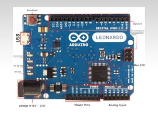
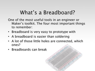
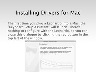
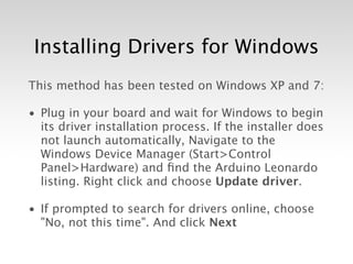
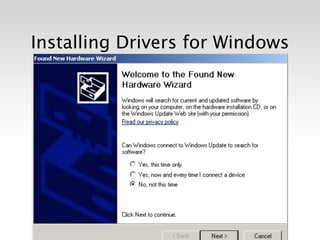
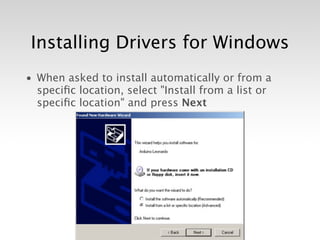
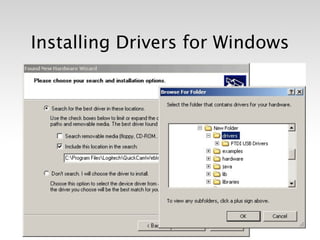
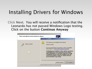
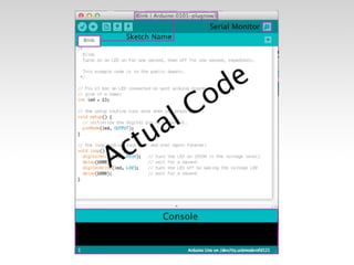
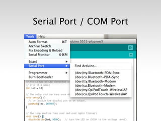
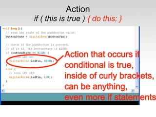
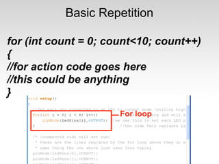
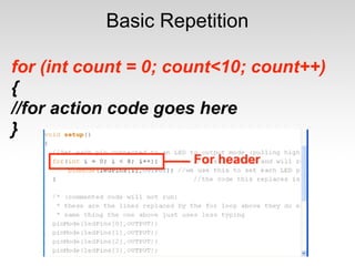
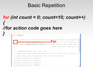
The document outlines an introductory Arduino class held at CrashSpace, covering the basics of Arduino boards, programming, and circuit designs. It discusses essential concepts such as analog vs. digital signals, input/output functions, and the use of breadboards. The document also includes installation instructions for drivers on both Mac and Windows, along with various coding examples and project circuits.


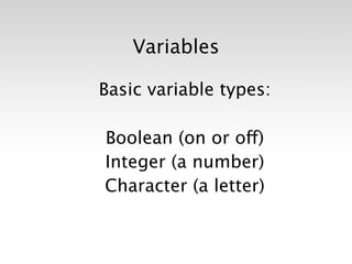
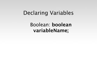
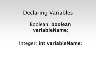
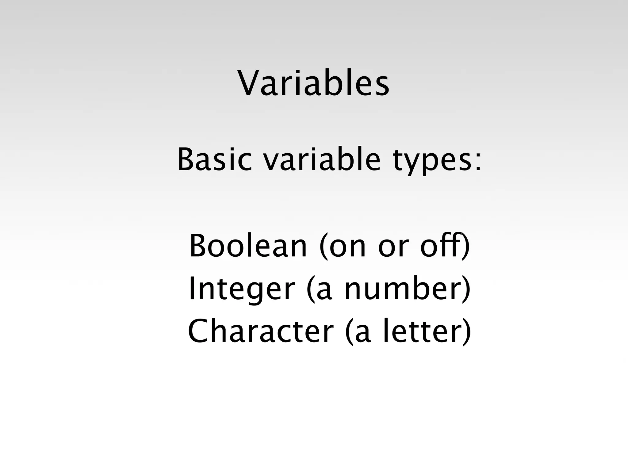
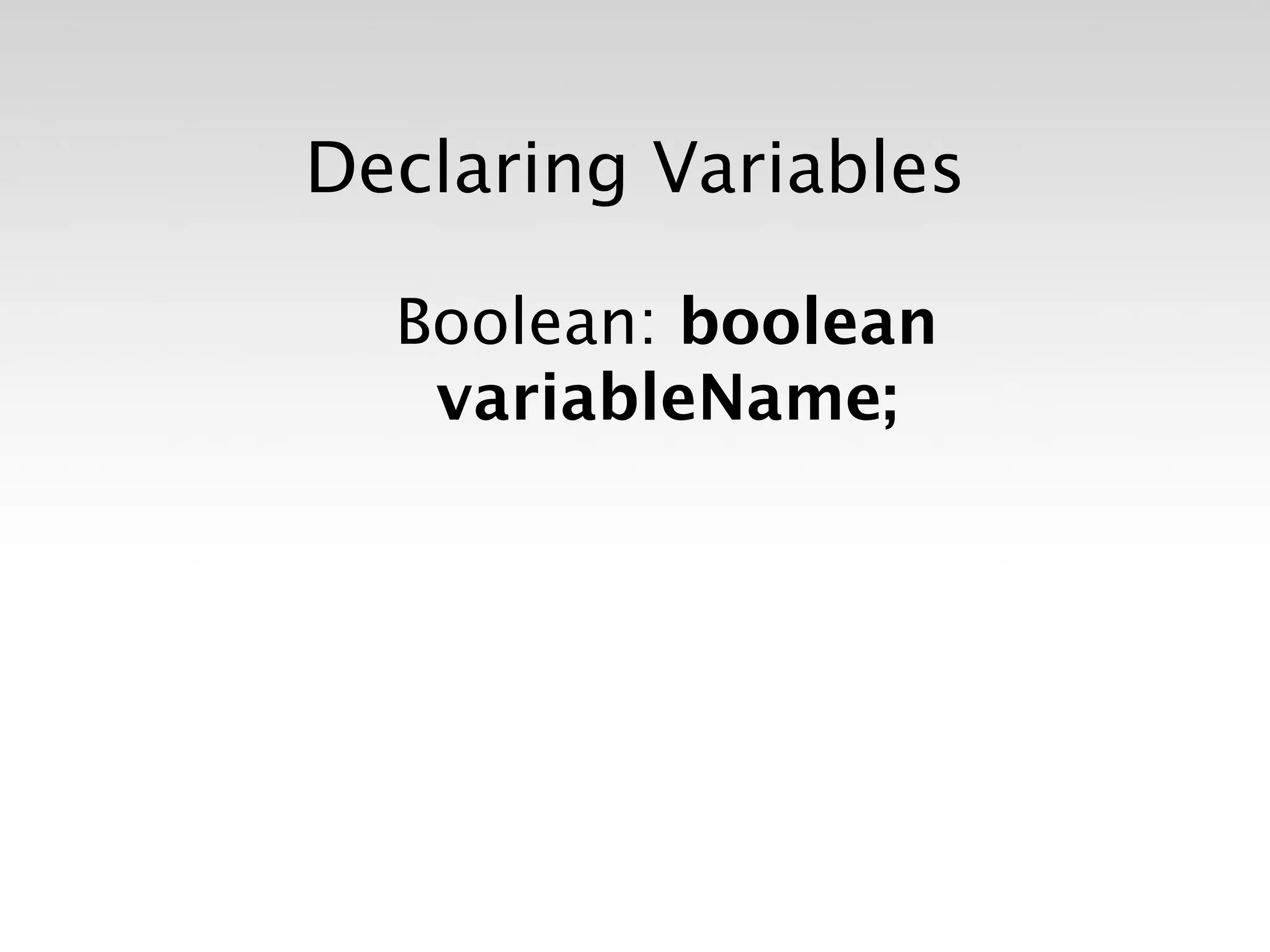
![Declaring Variables
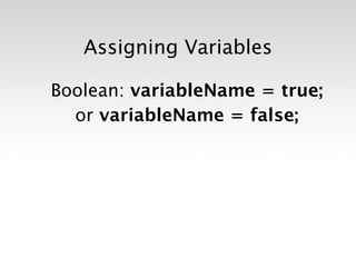
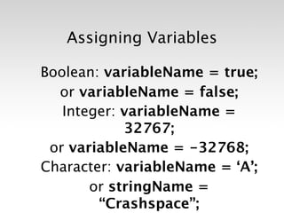
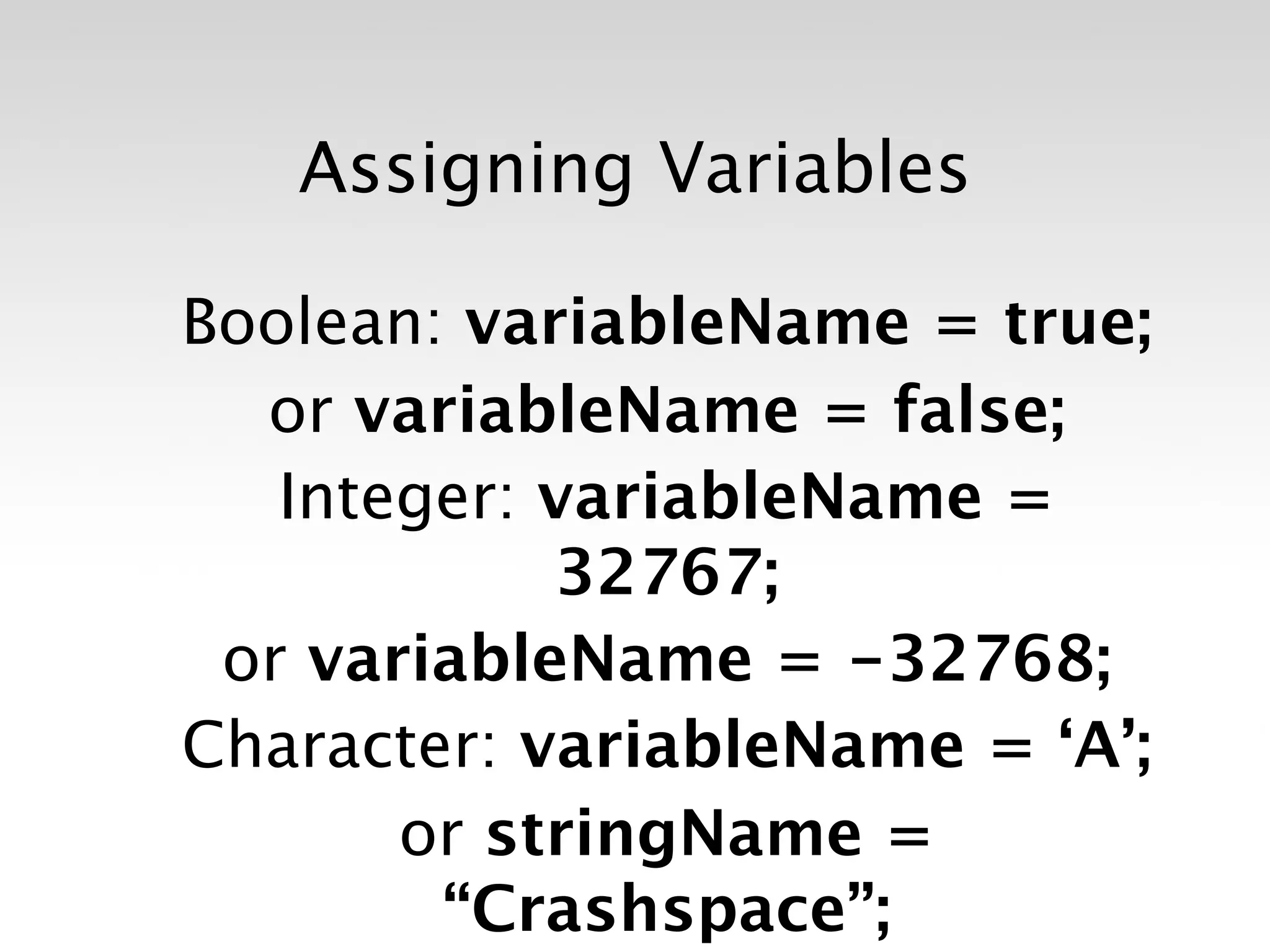
Boolean: boolean
variableName;
Integer: int variableName;
Character: char variableName;
String: stringName [ ];](https://image.slidesharecdn.com/introtoarduinoslideshare-120813172535-phpapp01/85/Intro-to-Arduino-61-320.jpg)


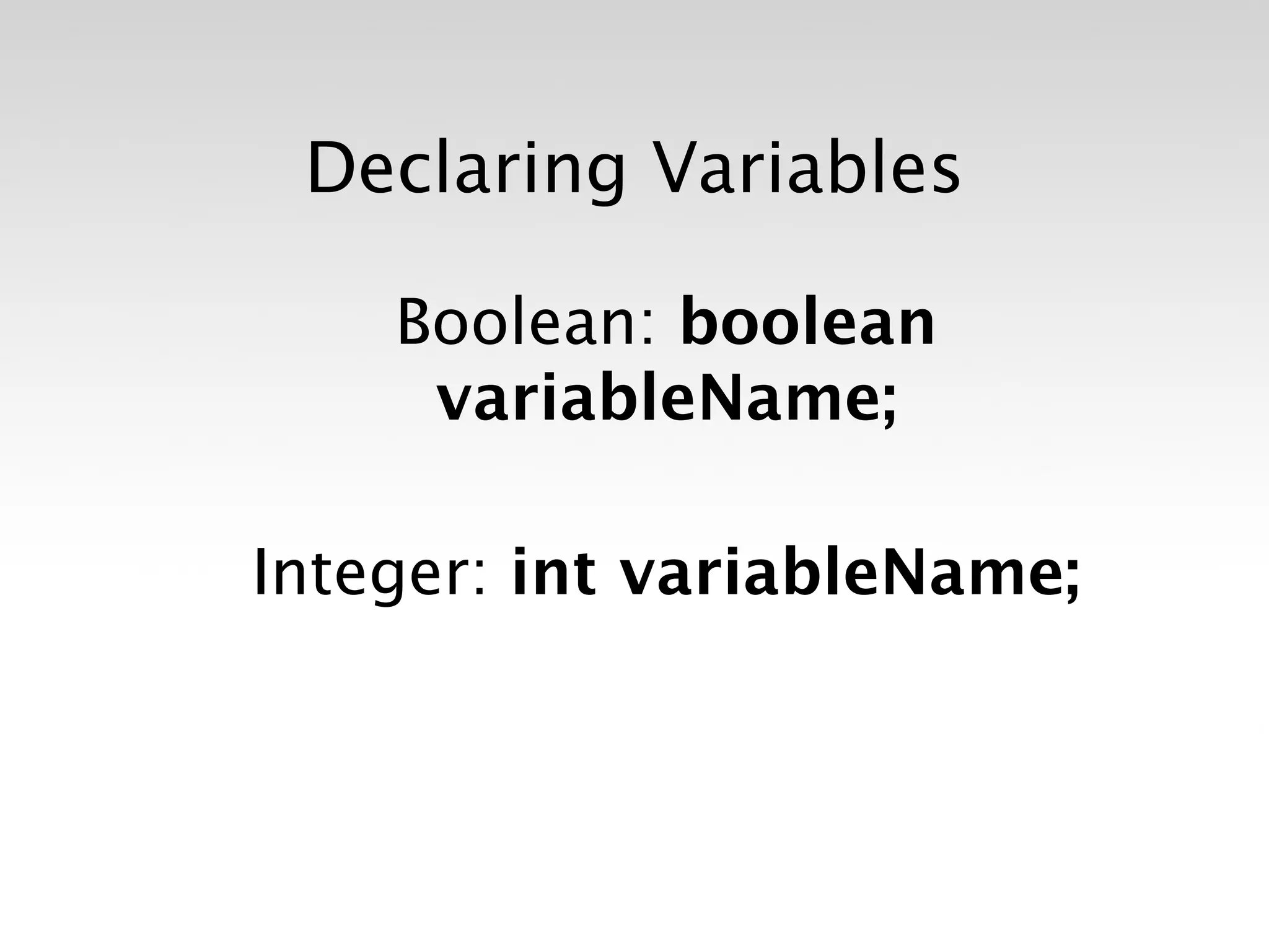
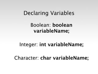
![Declaring Variables
Boolean: boolean
variableName;
Integer: int variableName;
Character: char variableName;
String: stringName [ ];](https://image.slidesharecdn.com/introtoarduinoslideshare-120813172535-phpapp01/75/Intro-to-Arduino-61-2048.jpg)


![Introduction to ESP32 Programming [Road to RIoT 2017]](https://cdn.slidesharecdn.com/ss_thumbnails/roadtoriotsurabayagettingstartedesp32-170726155154-thumbnail.jpg?width=600ounds&width=560&fit=bounds)


![UiPath Automation Suite Installation (Hands-On) [2/3]](https://cdn.slidesharecdn.com/ss_thumbnails/automationsuitecommunitysession2-251015095633-a6d862f1-thumbnail.jpg?width=600ounds&width=560&fit=bounds)


