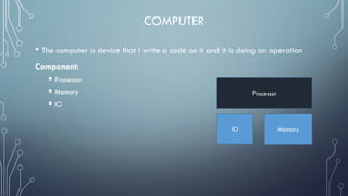
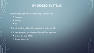
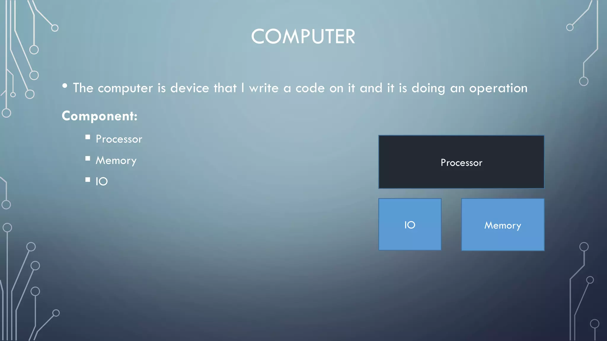
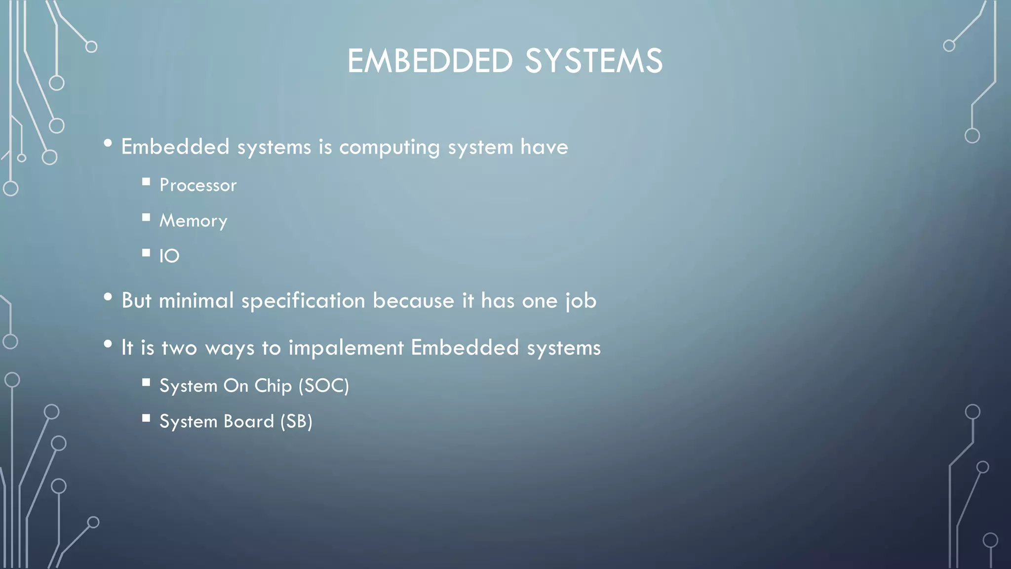
1) Embedded systems are computing systems that perform dedicated functions. They contain a processor, memory, and input/output components on a single chip or board.
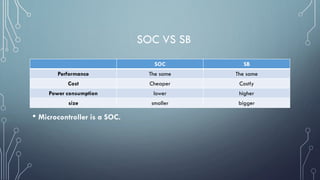
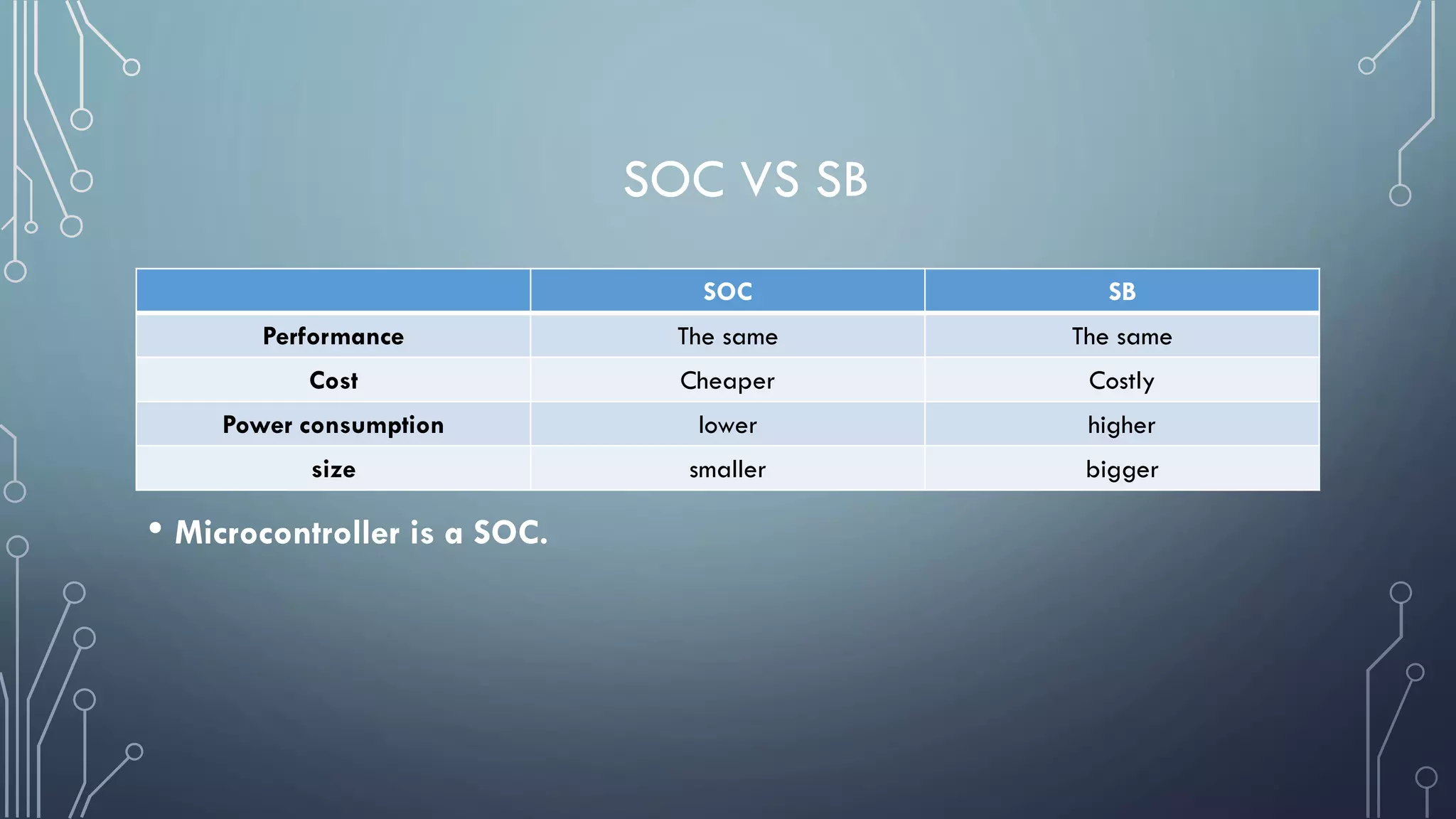
2) There are two main implementations of embedded systems - system on chip (SOC) and system board (SB). SOC is cheaper and uses less power, while SB is more costly but allows for higher performance.
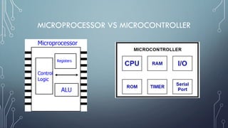
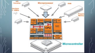
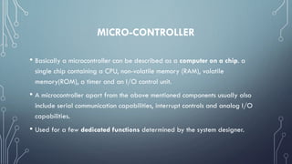
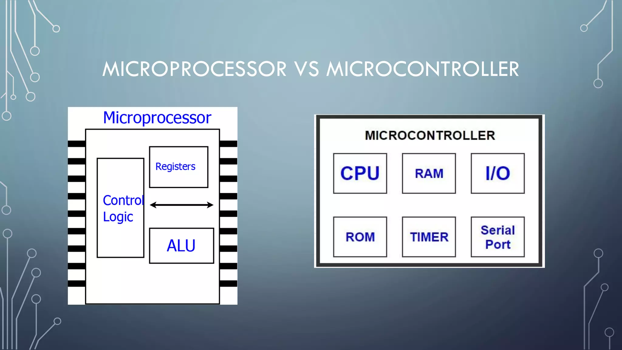
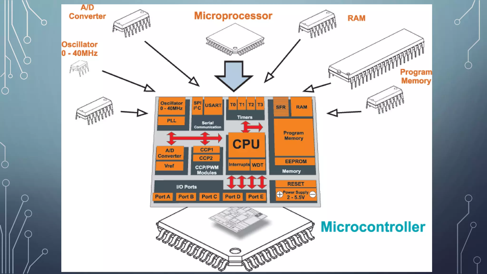
3) Microcontrollers are a type of SOC that contain a CPU, memory, and input/output control on a single chip. They are dedicated to specific tasks and commonly interface with sensors, switches, LEDs and other components.