This document provides an introduction to microcontrollers. It defines microcontrollers as small computers capable of performing specific tasks, like in appliances. Microcontrollers contain a CPU core, memory, input/output ports, timers and other peripherals on a single chip. They are classified as either microcontroller units (MCU) or microprocessor units (MPU) depending on whether external components are needed. Common microcontroller components and their functions are described, along with factors to consider when choosing a microcontroller for an application.
An introduction to the topic of microcontrollers, setting the framework for the following content.
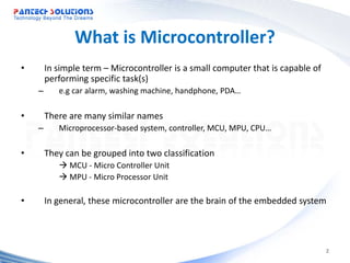
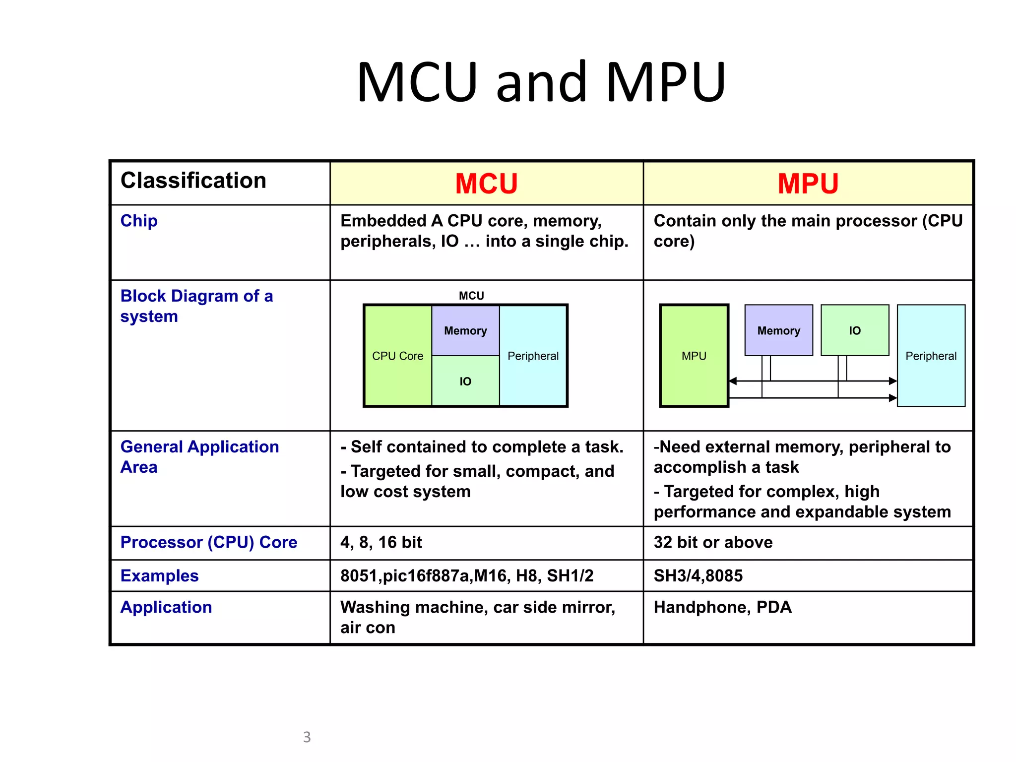
Microcontrollers (MCU) are small computing devices for specific tasks. Classifications include MCU and MPU, highlighting their roles in embedded systems.
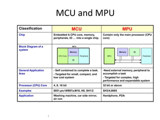
Comparison of MCU and MPU systems: MCUs are cost-effective and self-contained, while MPUs are complex with expandable systems.
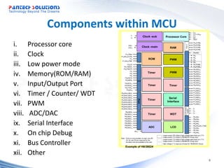
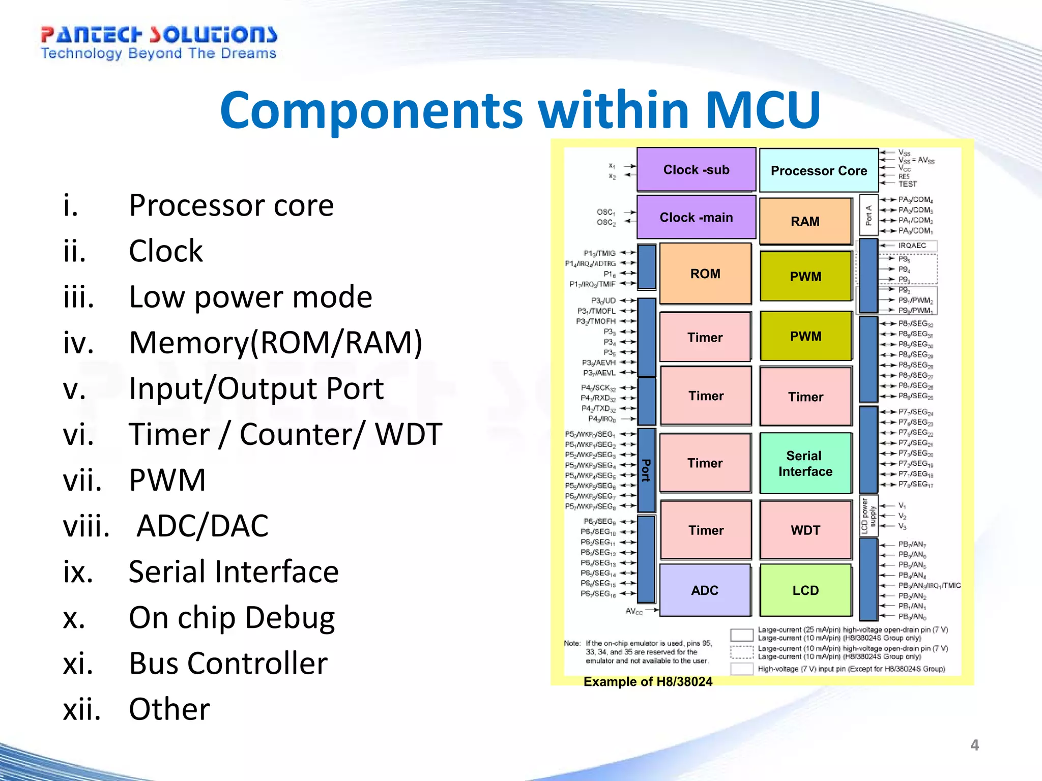
Overview of MCU components such as the processor core, clock, memory types (ROM/RAM), timers, and PWM.
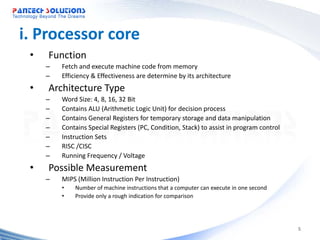
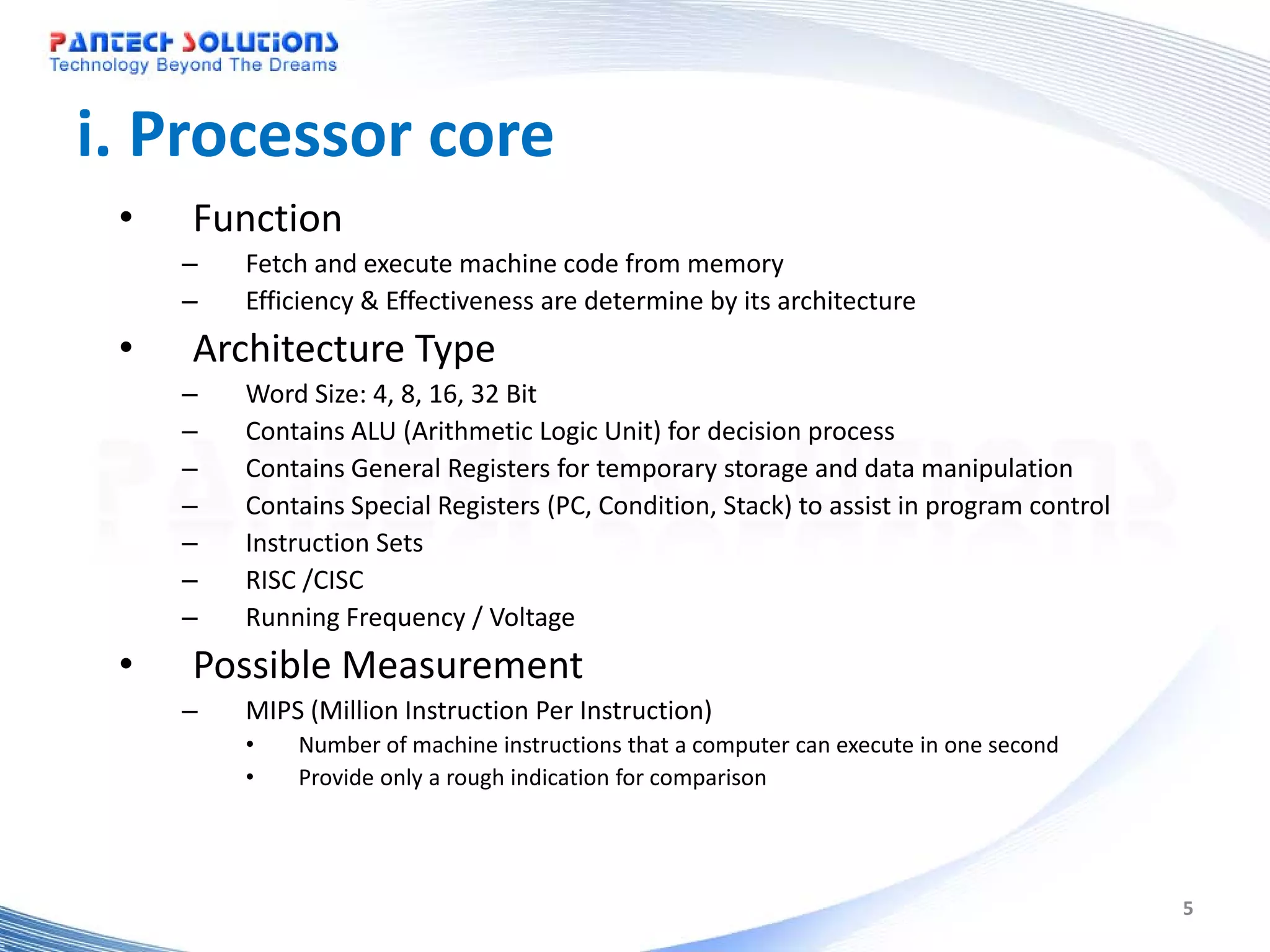
Processor core functions, architecture, and measurement via MIPS for assessing performance.
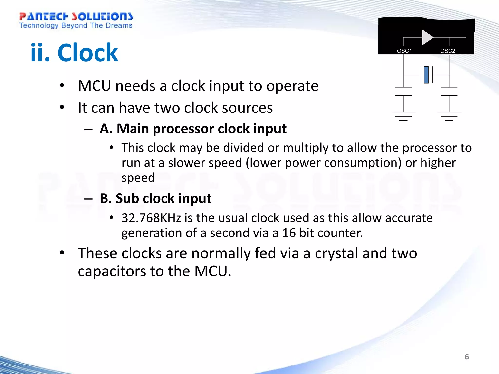
Explanation of MCU clock requirements and types, including main and sub clock sources for operation.
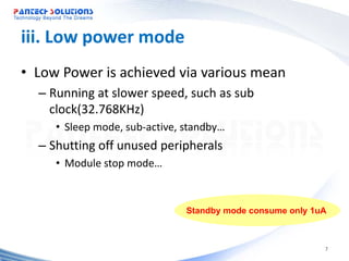
Methods for low power consumption in MCUs through speed adjustment and peripheral control.
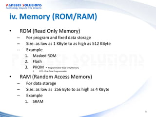
Details on ROM and RAM used in MCUs, including types and size ranges for applications.
I/O ports facilitate control and monitoring of external events, essential for MCU operations.
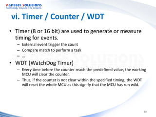
Introduction to timer functions in MCUs and the watchdog timer (WDT) for system reliability.
PWM application in generating control signals, particularly for motors.
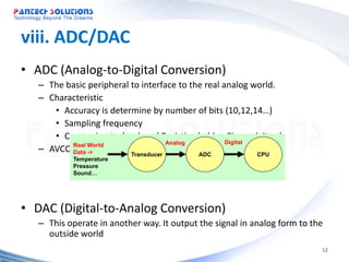
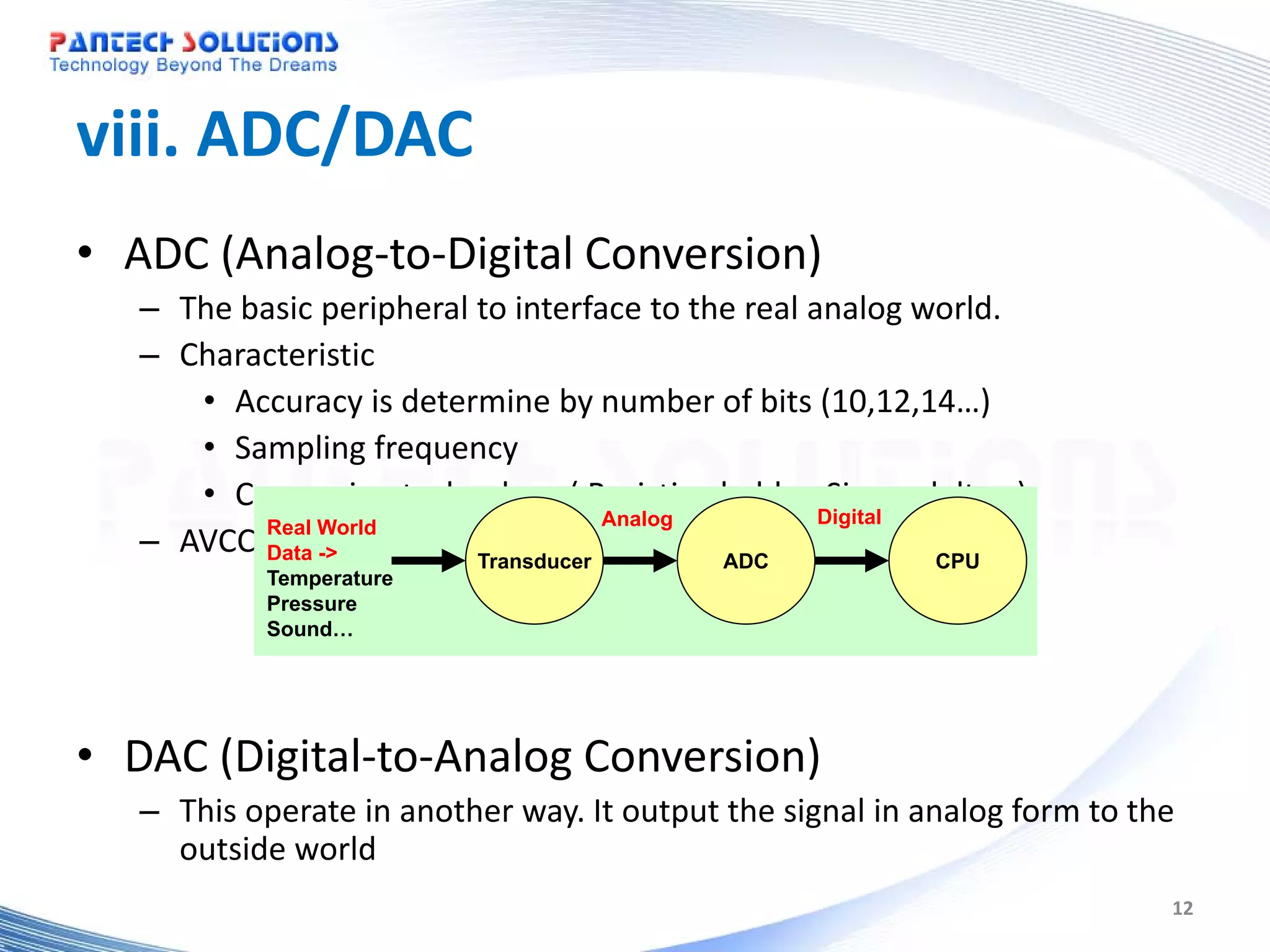
The roles of ADC and DAC in interfacing with analog and digital systems.
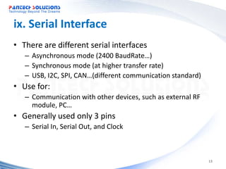
Overview of various serial interfaces for data communication in microcontroller systems.
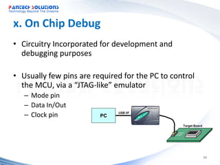
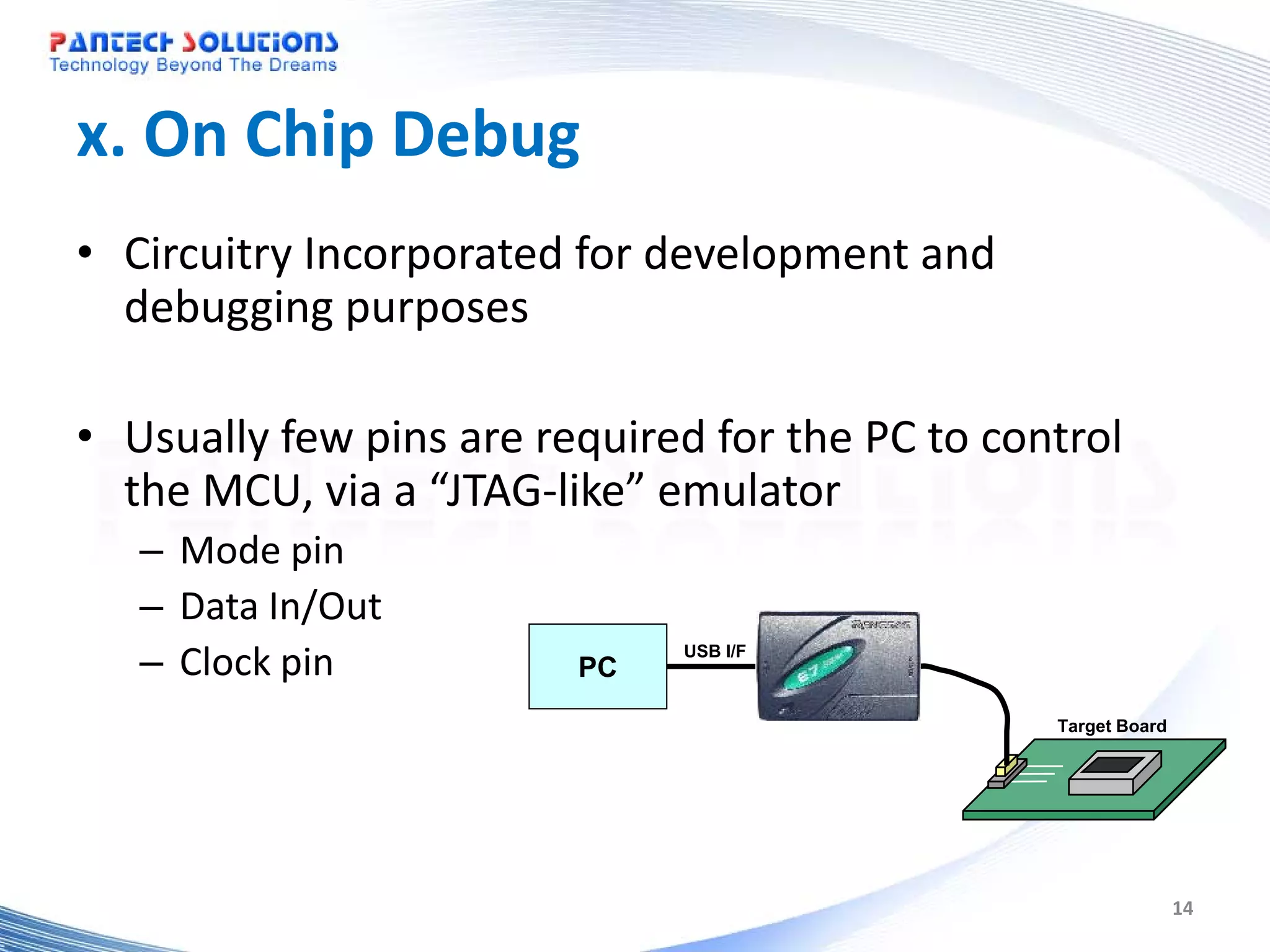
Description of debugging facilities incorporated within MCUs, including JTAG-like interfaces.
Functionality of bus controllers in managing memory operations within MCUs.
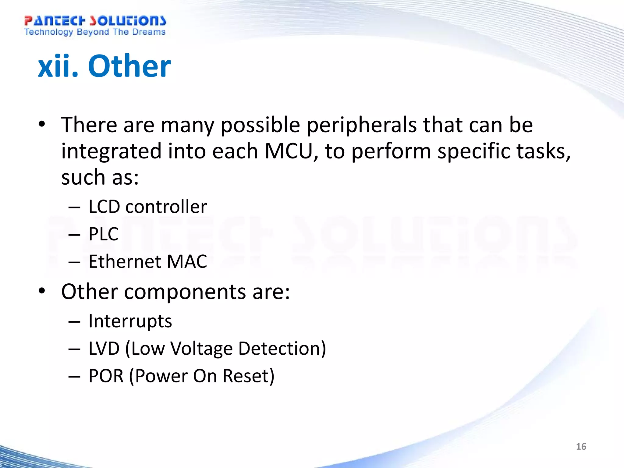
Various peripheral components that enhance MCU functionality, such as LCD controllers and interrupts.
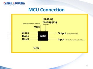
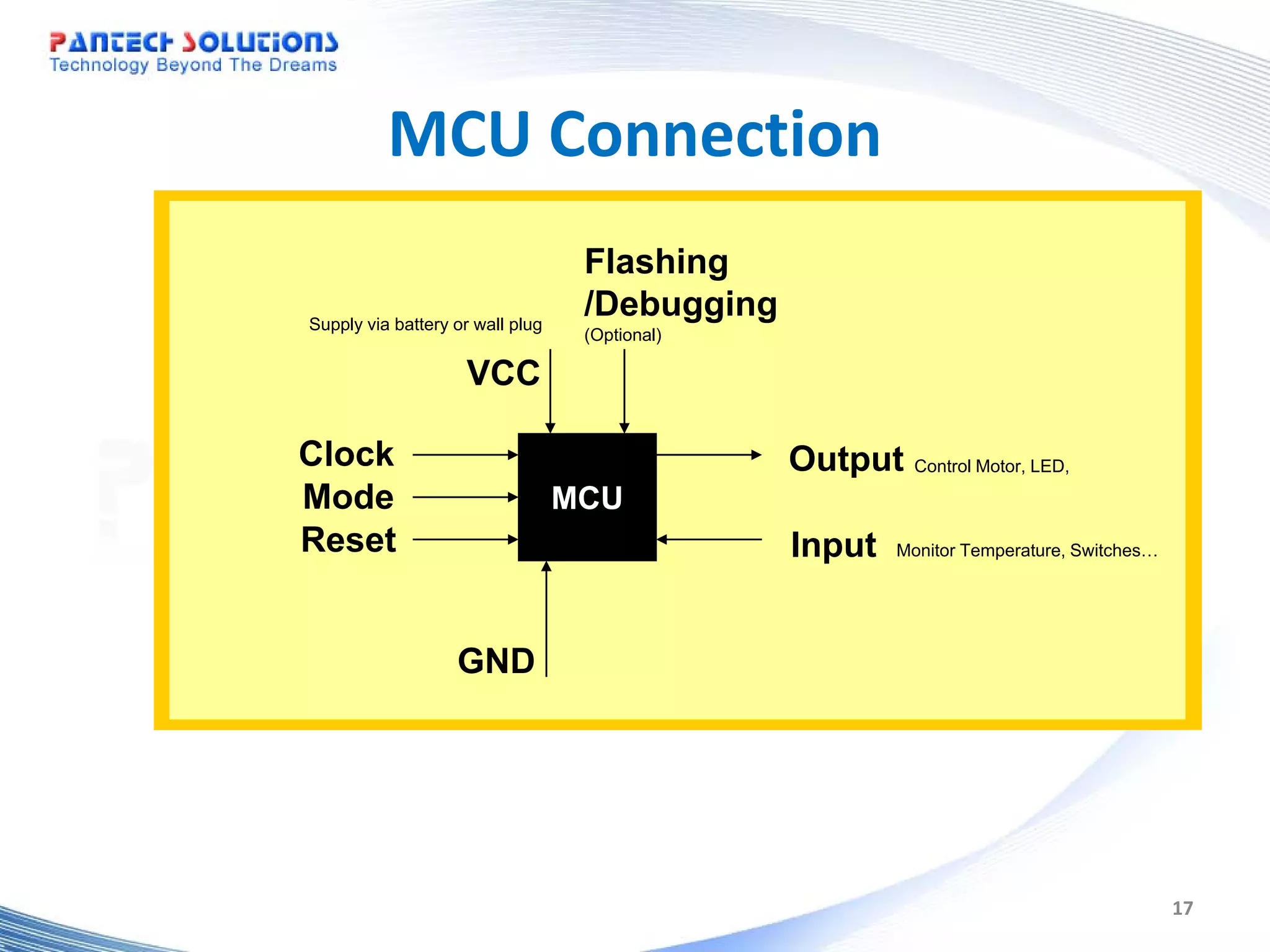
General description of MCU connections and operational components, including power supply and outputs.
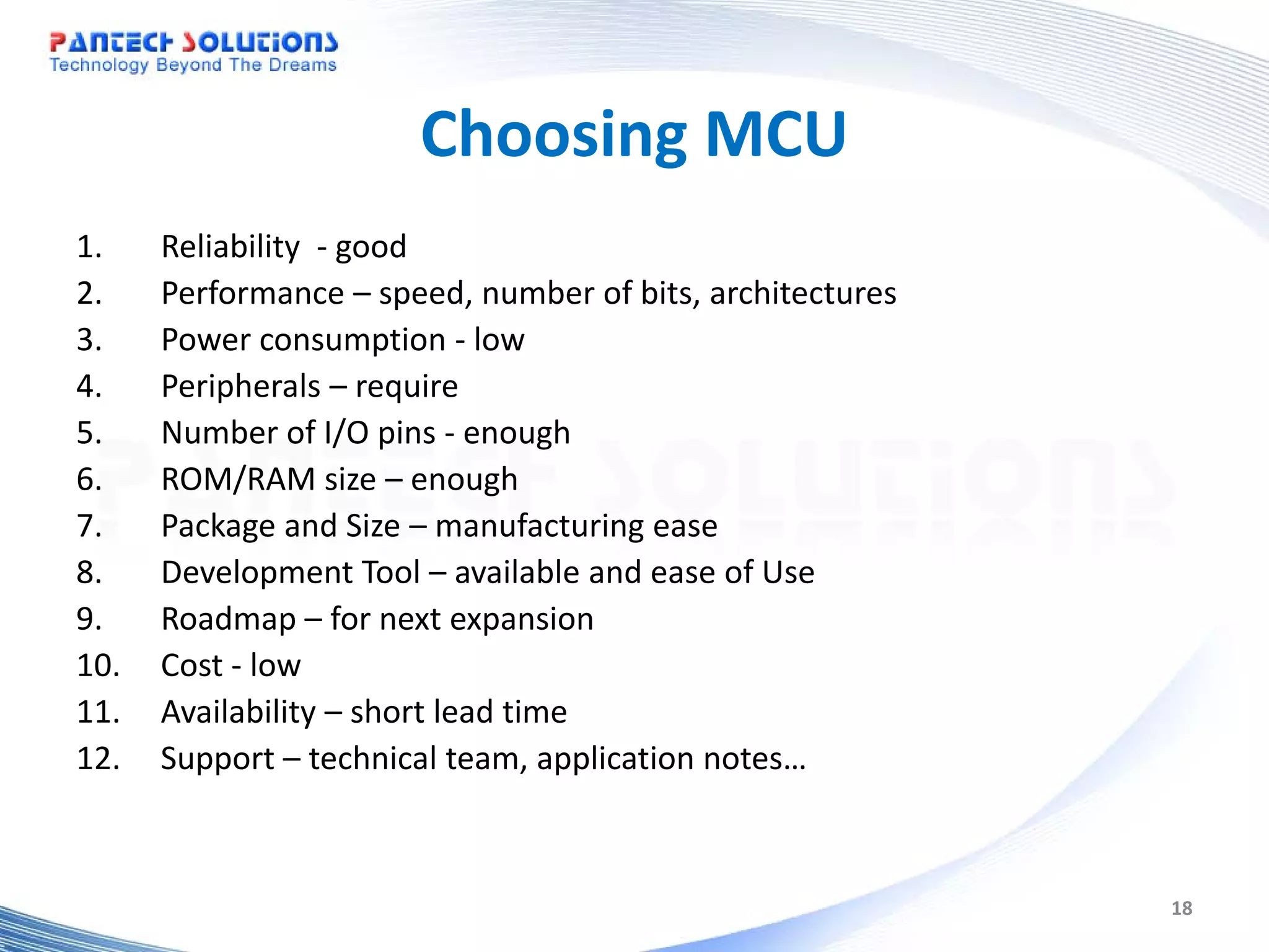
Key factors to consider when choosing a microcontroller, covering reliability, performance, and cost.
Links to additional resources and tutorials provided by Pantech Solutions for deeper understanding.
Introduction
to
Microcontroller
www.pantechsolutions.net
1
2.
What is Microcontroller?
• In simple term – Microcontroller is a small computer that is capable of
performing specific task(s)
– e.g car alarm, washing machine, handphone, PDA…
• There are many similar names
– Microprocessor-based system, controller, MCU, MPU, CPU…
• They can be grouped into two classification
MCU - Micro Controller Unit
MPU - Micro Processor Unit
• In general, these microcontroller are the brain of the embedded system
2
3.
MCU and MPU
Classification MCU MPU
Chip Embedded A CPU core, memory, Contain only the main processor (CPU
peripherals, IO … into a single chip. core)
Block Diagram of a MCU
system
Memory Memory IO
CPU Core Peripheral MPU Peripheral
IO
General Application - Self contained to complete a task. -Need external memory, peripheral to
Area - Targeted for small, compact, and accomplish a task
low cost system - Targeted for complex, high
performance and expandable system
Processor (CPU) Core 4, 8, 16 bit 32 bit or above
Examples 8051,pic16f887a,M16, H8, SH1/2 SH3/4,8085
Application Washing machine, car side mirror, Handphone, PDA
air con
3
4.
Components within MCU
Clock -sub Processor Core
i. Processor core Clock -main RAM
ii. Clock ROM PWM
iii. Low power mode
iv. Memory(ROM/RAM) Timer PWM
v. Input/Output Port Timer Timer
vi. Timer / Counter/ WDT Serial
vii. PWM
Timer
Port
Interface
viii. ADC/DAC Timer WDT
ix. Serial Interface ADC LCD
x. On chip Debug
xi. Bus Controller Example of H8/38024
xii. Other
4
5.
i. Processor core
• Function
– Fetch and execute machine code from memory
– Efficiency & Effectiveness are determine by its architecture
• Architecture Type
– Word Size: 4, 8, 16, 32 Bit
– Contains ALU (Arithmetic Logic Unit) for decision process
– Contains General Registers for temporary storage and data manipulation
– Contains Special Registers (PC, Condition, Stack) to assist in program control
– Instruction Sets
– RISC /CISC
– Running Frequency / Voltage
• Possible Measurement
– MIPS (Million Instruction Per Instruction)
• Number of machine instructions that a computer can execute in one second
• Provide only a rough indication for comparison
5
6.
ii. Clock OSC1 OSC2
• MCU needs a clock input to operate
• It can have two clock sources
– A. Main processor clock input
• This clock may be divided or multiply to allow the processor to
run at a slower speed (lower power consumption) or higher
speed
– B. Sub clock input
• 32.768KHz is the usual clock used as this allow accurate
generation of a second via a 16 bit counter.
• These clocks are normally fed via a crystal and two
capacitors to the MCU.
6
7.
iii. Low powermode
• Low Power is achieved via various mean
– Running at slower speed, such as sub
clock(32.768KHz)
• Sleep mode, sub-active, standby…
– Shutting off unused peripherals
• Module stop mode…
Standby mode consume only 1uA
7
8.
iv. Memory (ROM/RAM)
• ROM (Read Only Memory)
– For program and fixed data storage
– Size: as low as 1 KByte to as high as 512 KByte
– Example
1. Masked ROM
2. Flash
3. PROM - Programmable Read-Only Memory
1. OTP - One-Time Programmable
• RAM (Random Access Memory)
– For data storage
– Size: as low as 256 Byte to as high as 4 KByte
– Example
1. SRAM
8
9.
v. Input /Output Port
• Basic interface to control (output) and
monitor (Input) external events.
– High current port
• (20mA), so as to drive LED directly.
– Open-collector/drain port
• Interface to higher supply circuitry
• Wired-Nor condition
9
10.
vi. Timer /Counter / WDT
• Timer (8 or 16 bit) are used to generate or measure
timing for events.
– External event trigger the count
– Compare match to perform a task
– …
• WDT (WatchDog Timer)
– Every time before the counter reach the predefined value, the working
MCU will clear the counter.
– Thus, if the counter is not clear within the specified timing, the WDT
will reset the whole MCU as this signify that the MCU has run wild.
10
11.
vii. PWM
• PWM(Pulse Width Modulation)
– Generate continue pulse of preset duty cycle
• This can be used to drive motor.
11
12.
viii. ADC/DAC
• ADC(Analog-to-Digital Conversion)
– The basic peripheral to interface to the real analog world.
– Characteristic
• Accuracy is determine by number of bits (10,12,14…)
• Sampling frequency
• Conversion technology ( Resistive ladder, Sigma delta…)
Analog Digital
– AVCC, Data -> and eachTransducer input pins
AVSS
Real World
analog ADC CPU
Temperature
Pressure
Sound…
• DAC (Digital-to-Analog Conversion)
– This operate in another way. It output the signal in analog form to the
outside world
12
13.
ix. Serial Interface
•There are different serial interfaces
– Asynchronous mode (2400 BaudRate…)
– Synchronous mode (at higher transfer rate)
– USB, I2C, SPI, CAN…(different communication standard)
• Use for:
– Communication with other devices, such as external RF
module, PC…
• Generally used only 3 pins
– Serial In, Serial Out, and Clock
13
14.
x. On ChipDebug
• Circuitry Incorporated for development and
debugging purposes
• Usually few pins are required for the PC to control
the MCU, via a “JTAG-like” emulator
– Mode pin
– Data In/Out
– Clock pin PC
USB I/F
Target Board
14
15.
xi. Bus Controller
•In the higher performance MCU, a bus controller is
incorporated to manage internal and external
memory bus.
• The external bus may be split into different areas, so
that each area can be assigned with different setting
– Refresh controller for DRAM
– Longer wait cycles for slower devices
15
16.
xii. Other
• Thereare many possible peripherals that can be
integrated into each MCU, to perform specific tasks,
such as:
– LCD controller
– PLC
– Ethernet MAC
• Other components are:
– Interrupts
– LVD (Low Voltage Detection)
– POR (Power On Reset)
16
17.
MCU Connection
Flashing
Supply via battery or wall plug
/Debugging
(Optional)
VCC
Clock Output Control Motor, LED,
Mode MCU
Reset Input Monitor Temperature, Switches…
GND
17
18.
Choosing MCU
1. Reliability - good
2. Performance – speed, number of bits, architectures
3. Power consumption - low
4. Peripherals – require
5. Number of I/O pins - enough
6. ROM/RAM size – enough
7. Package and Size – manufacturing ease
8. Development Tool – available and ease of Use
9. Roadmap – for next expansion
10. Cost - low
11. Availability – short lead time
12. Support – technical team, application notes…
18