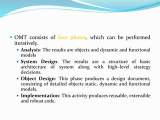
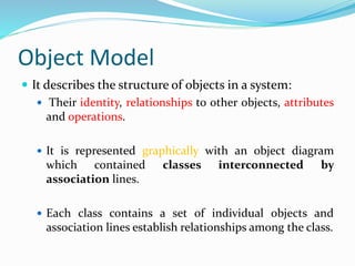
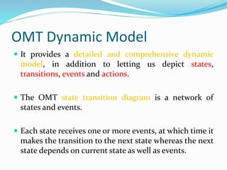
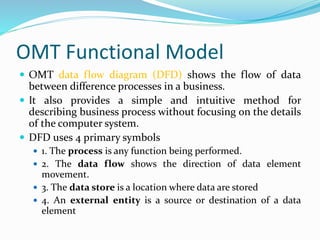
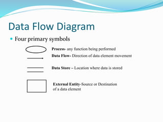
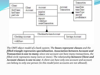
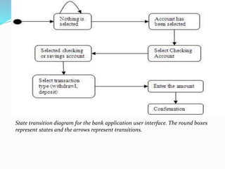
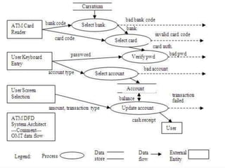
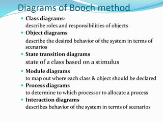
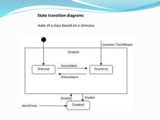
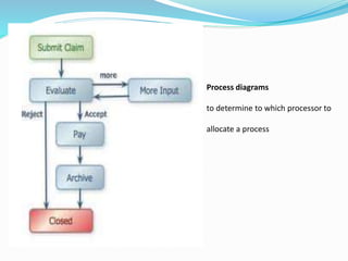
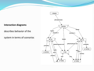
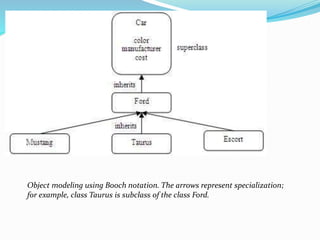
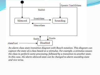
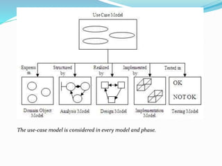
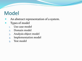
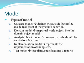
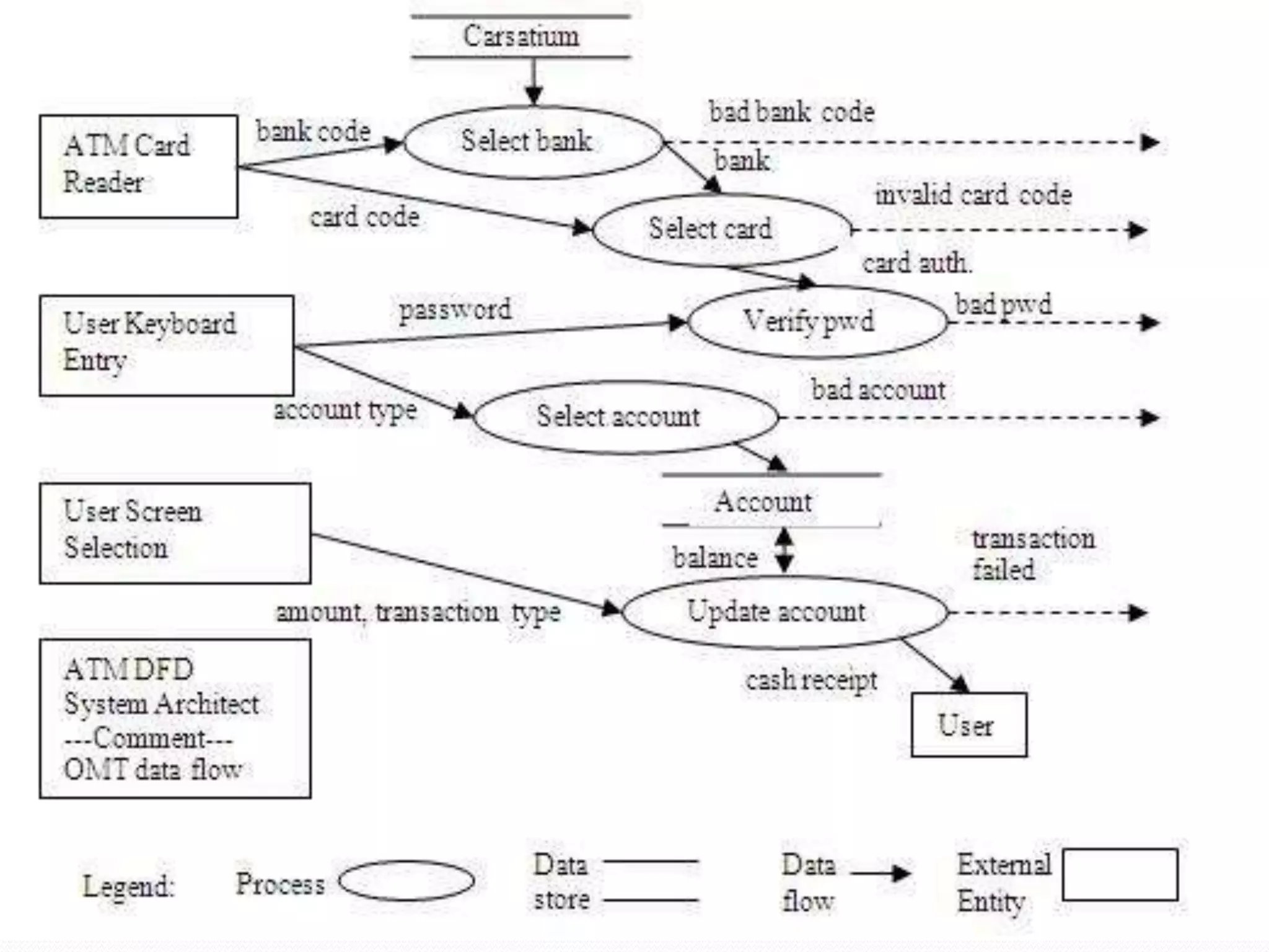
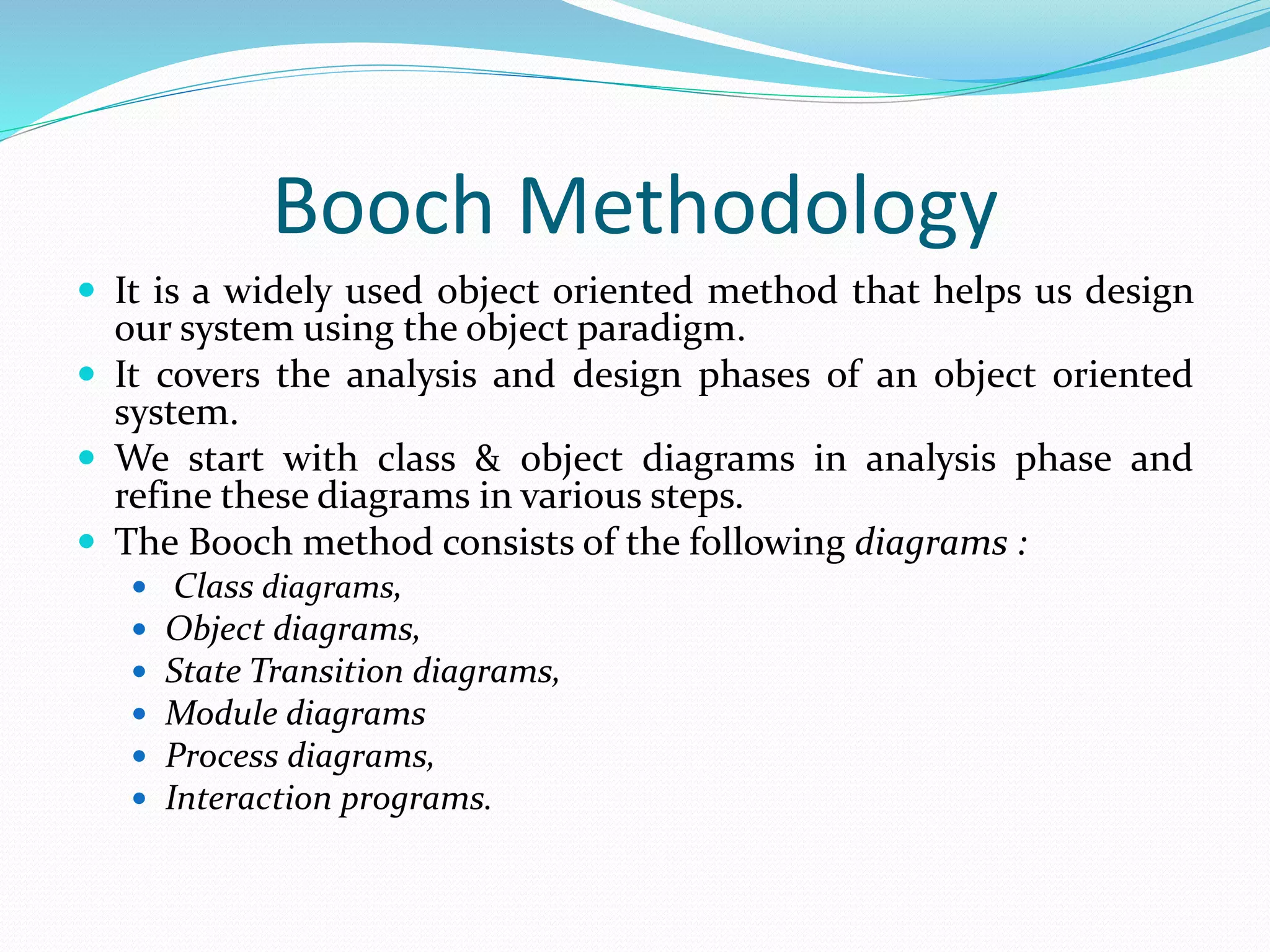
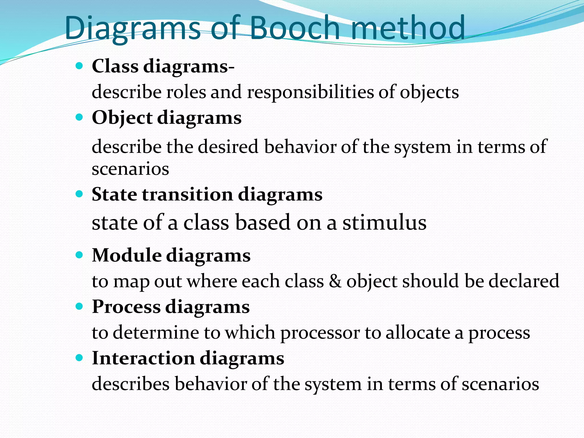
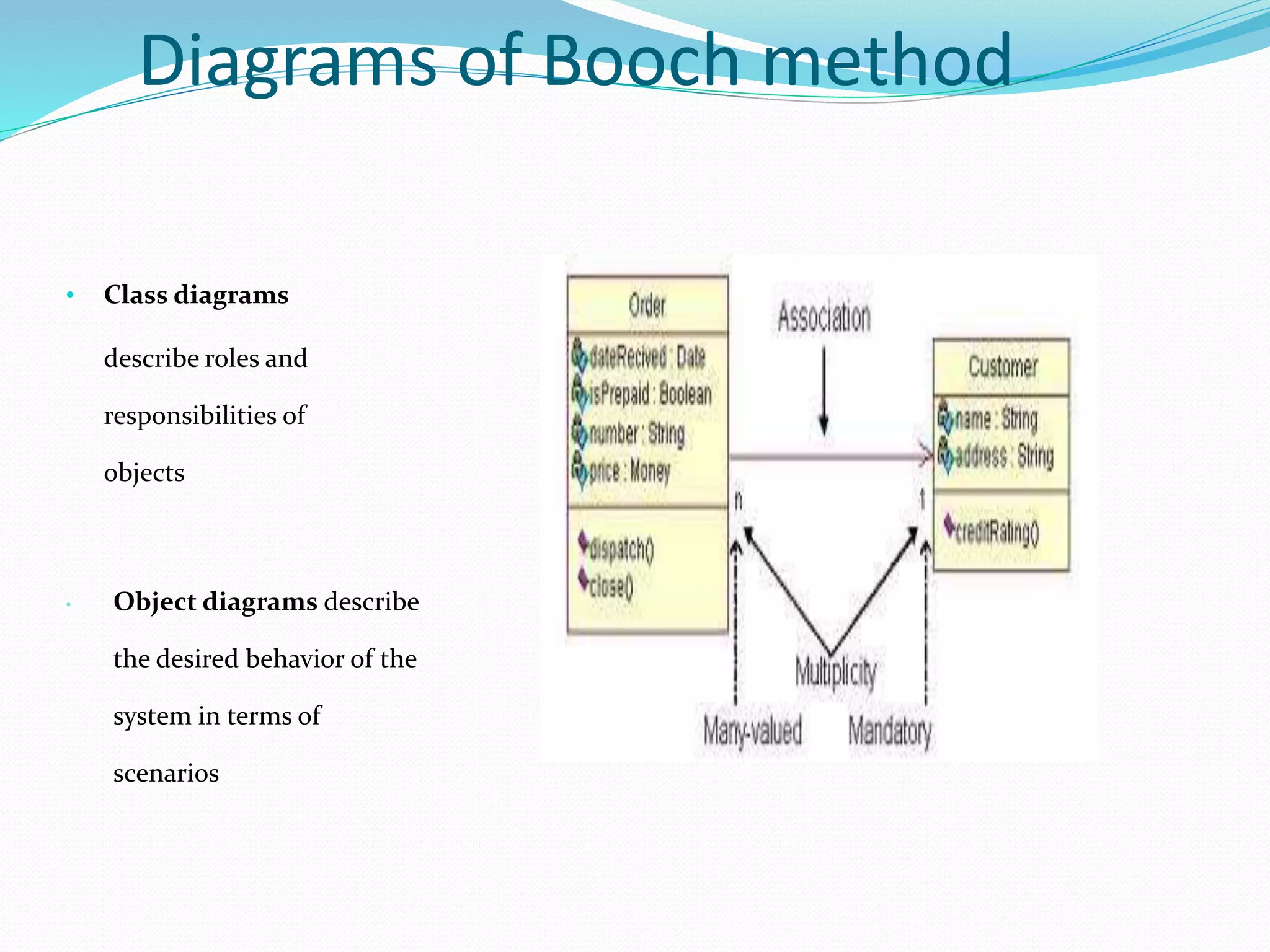
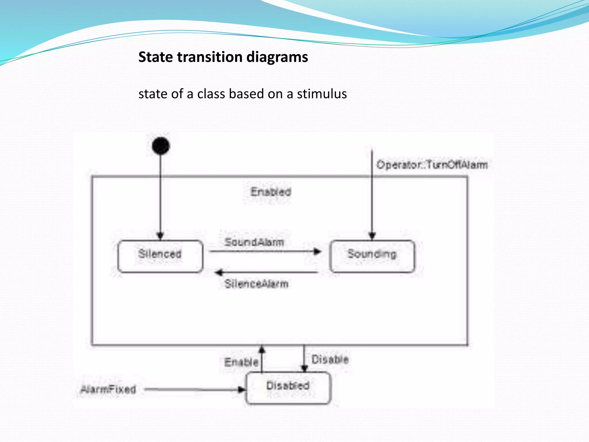
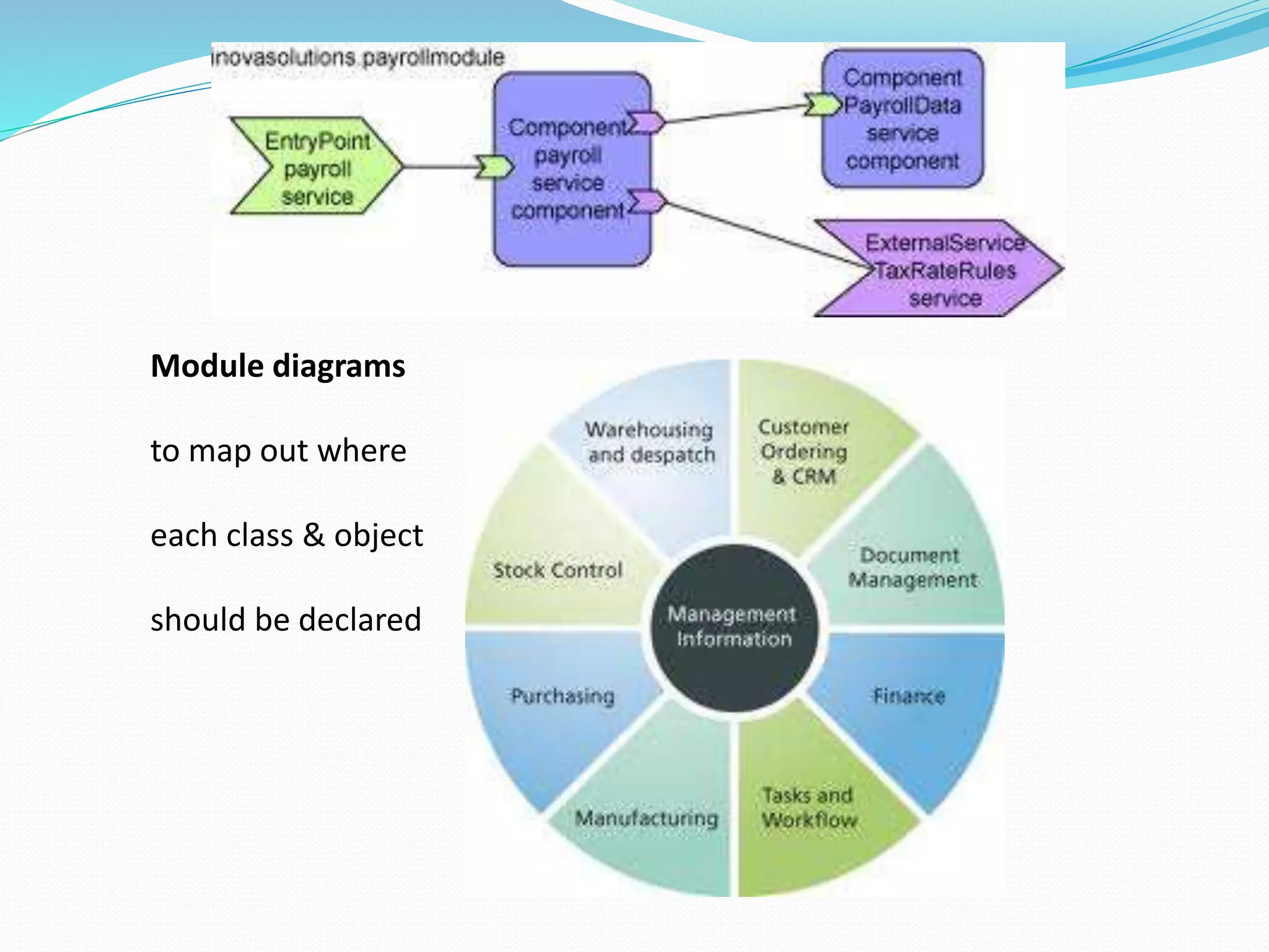
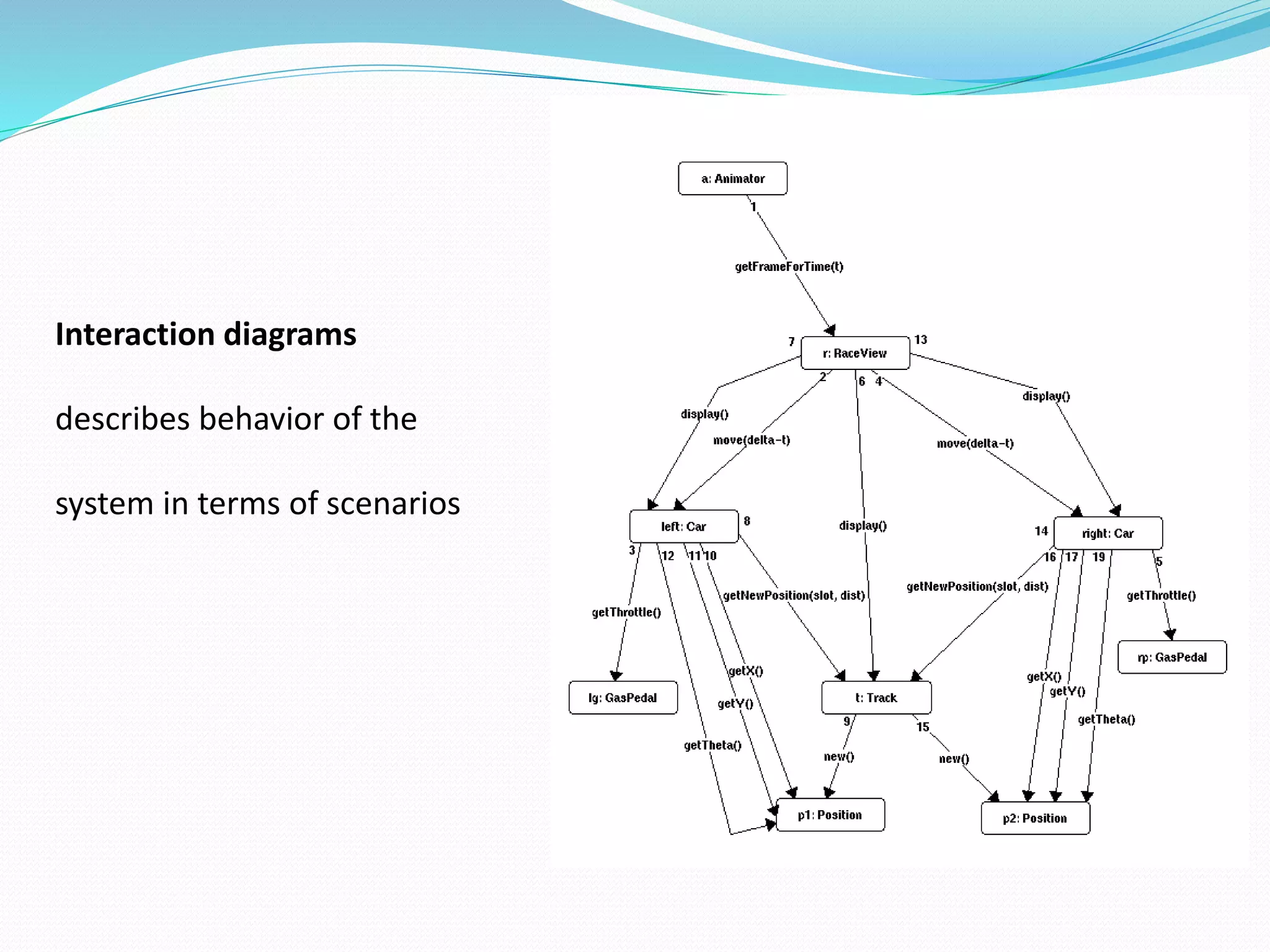
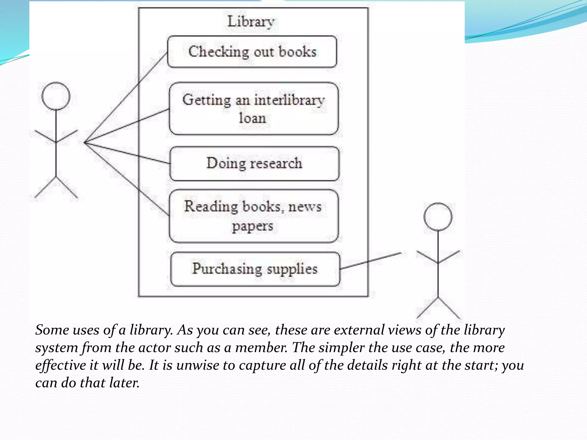
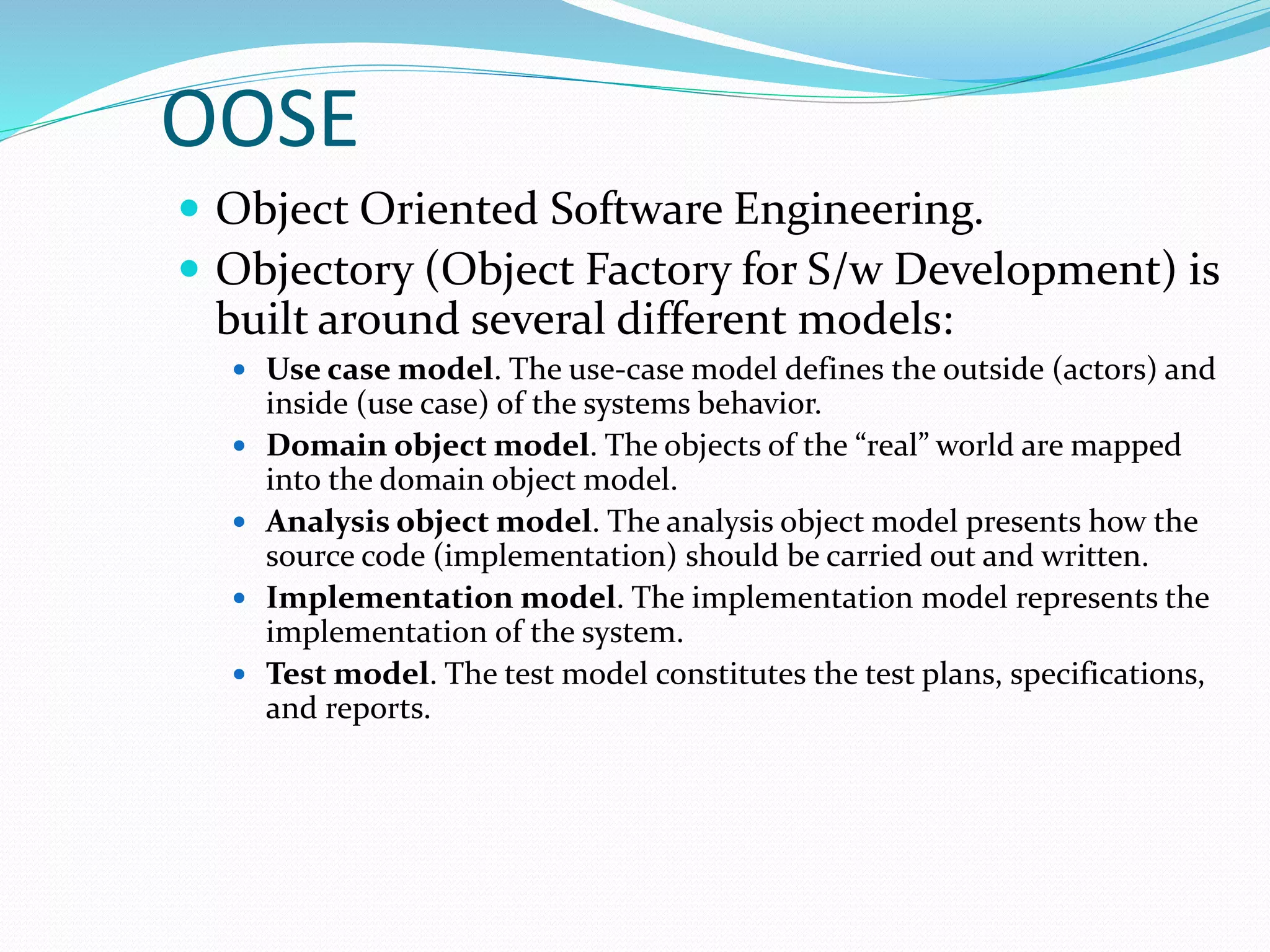
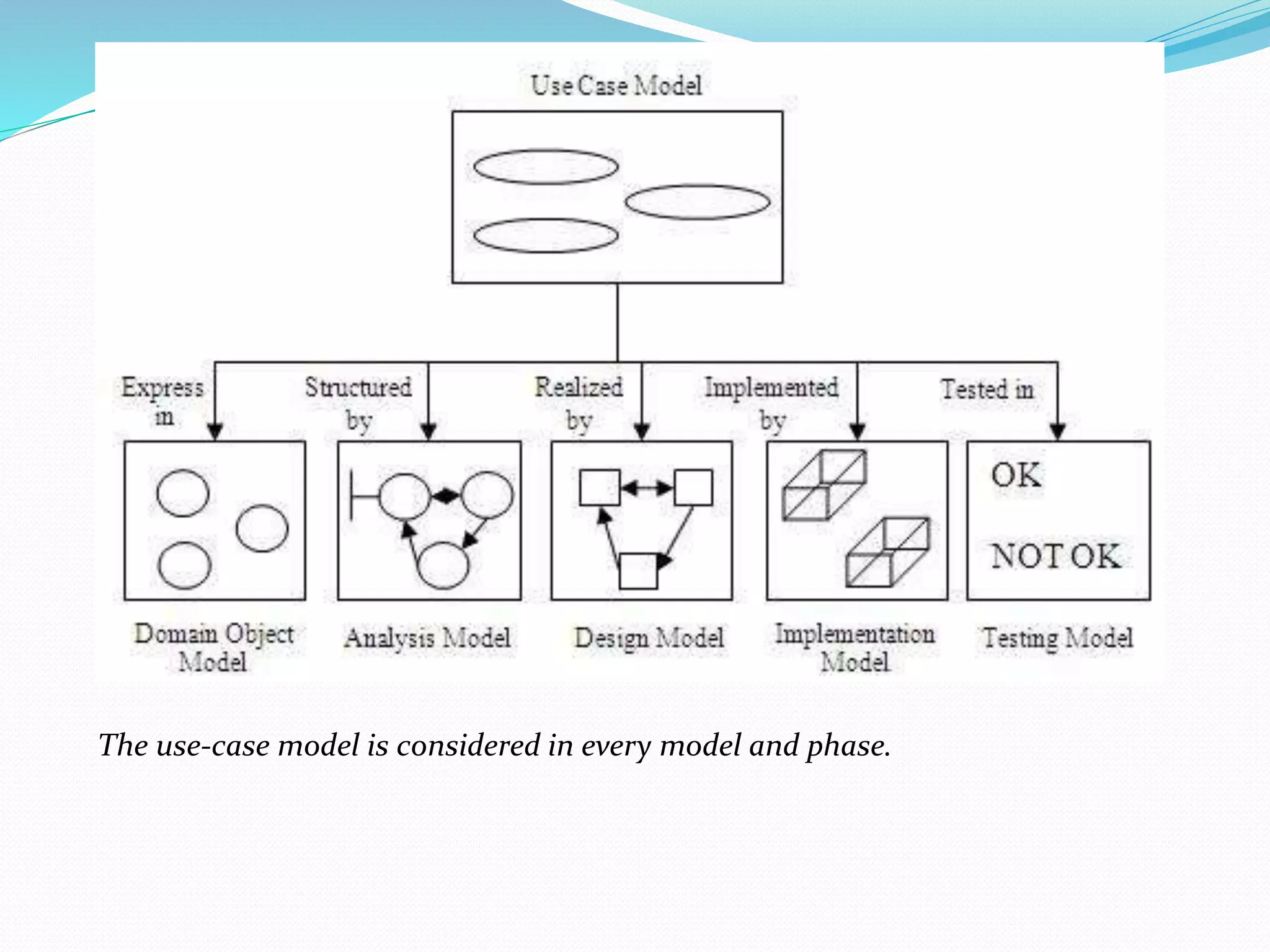
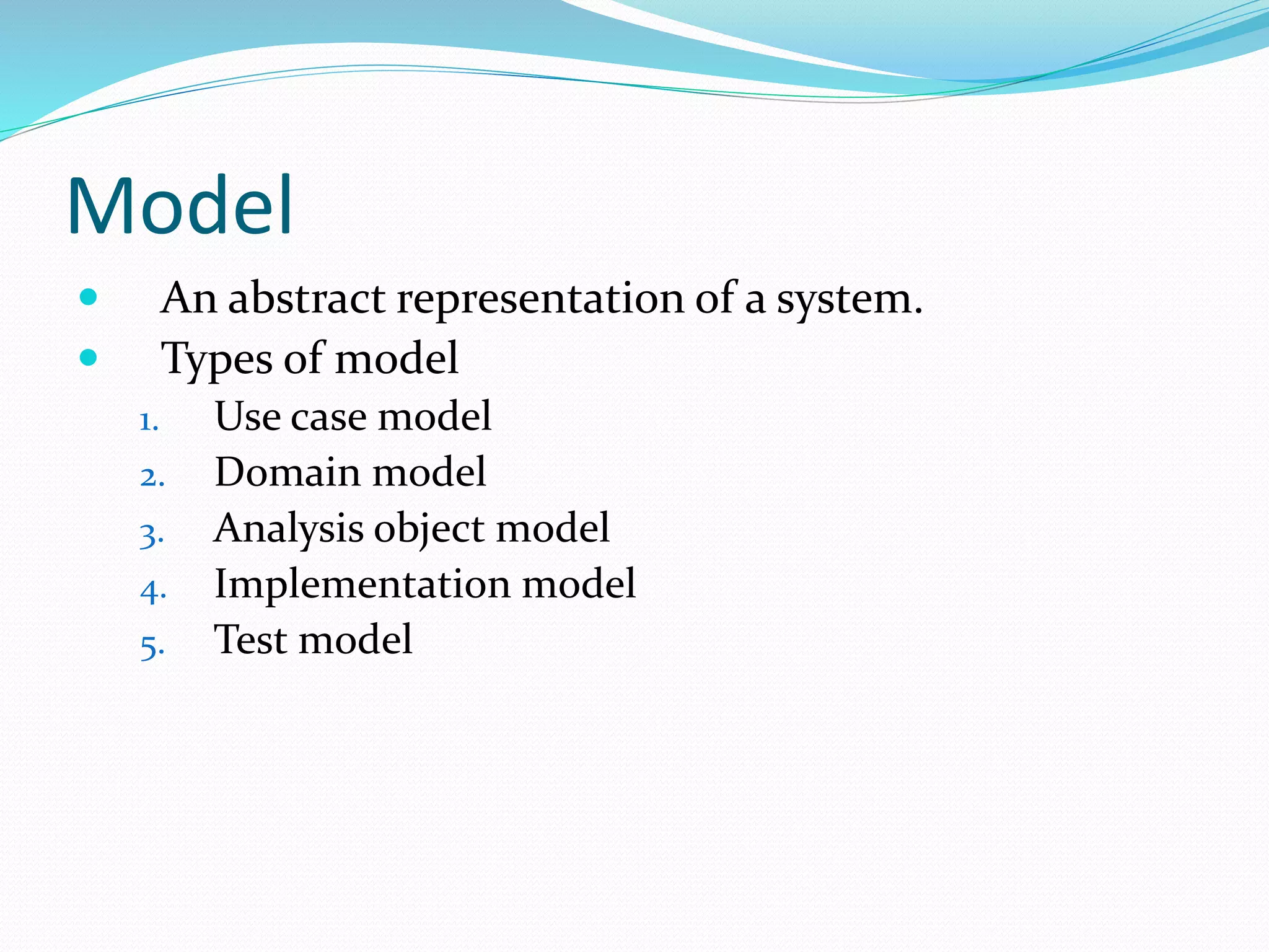
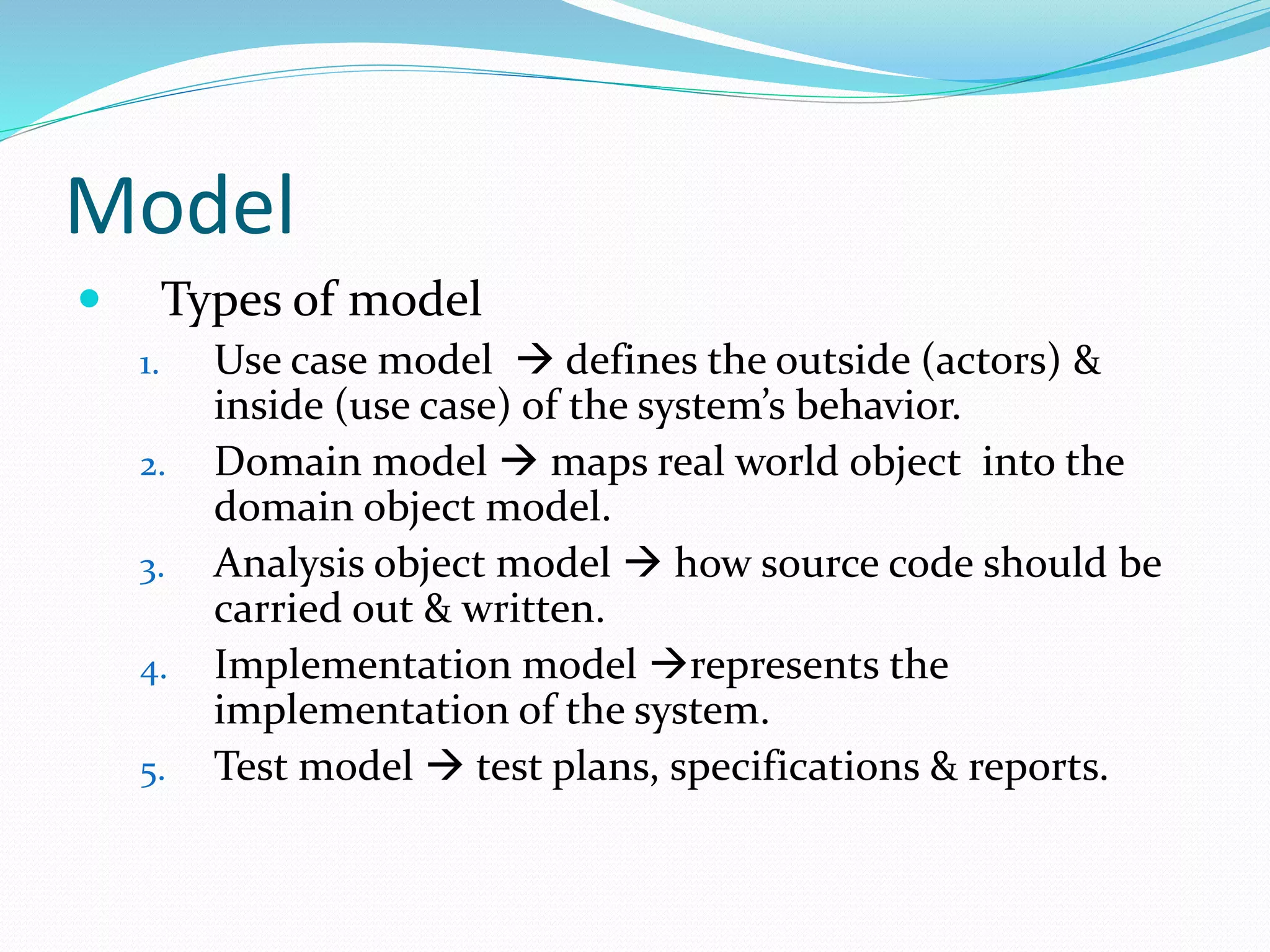
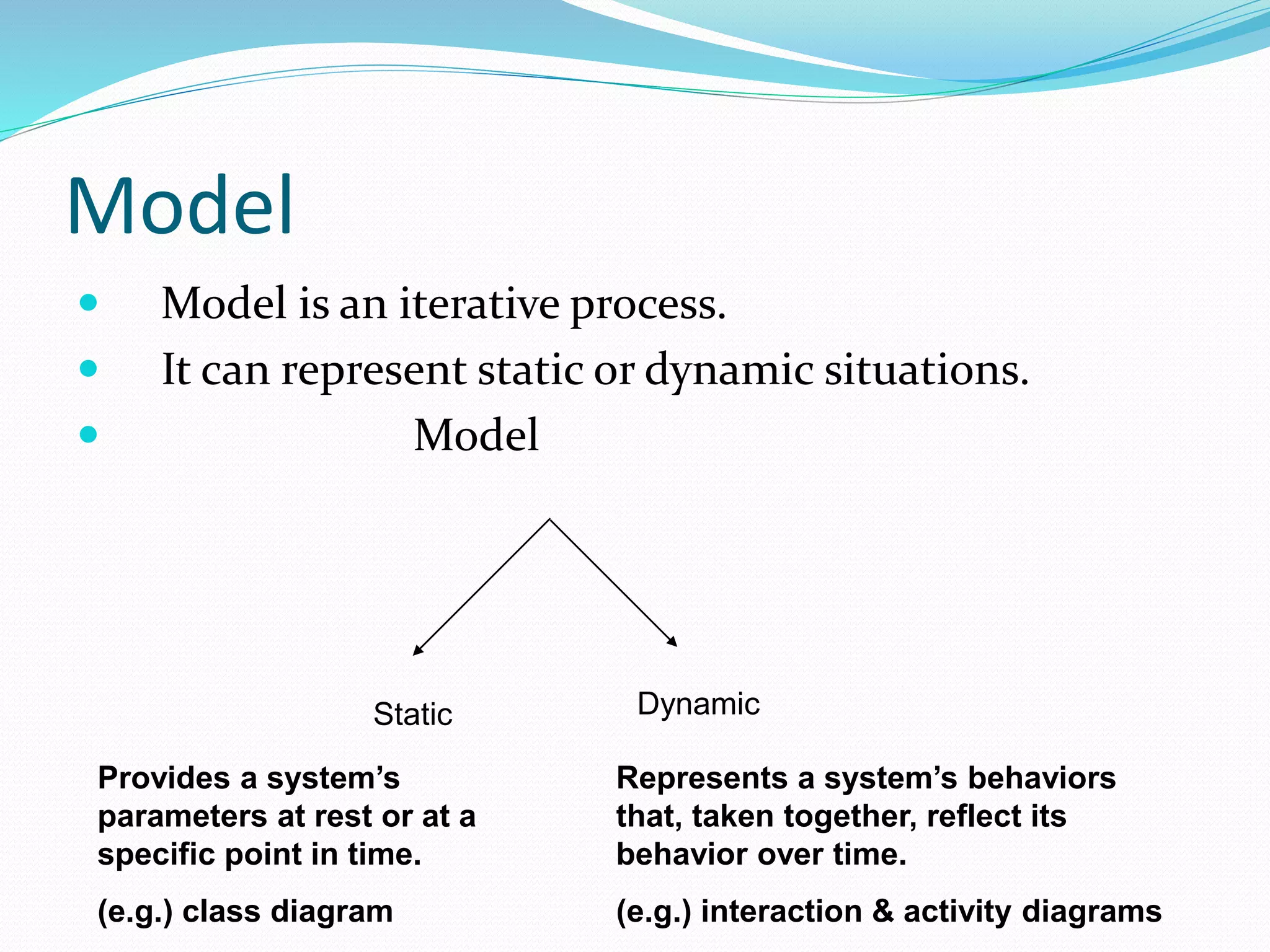
KEMBAR78
object oriented methodologies | PPTX
Object Oriented Methodologies
Introduction
 A system of methods used in a particular area of
study or activity
 Numbers of methodology are based on modeling the
business problem and implementing the application
in an object oriented fashion.
 The major differences between different
methodologies lie primarily in the documentation of
information, and modeling notations and language.
 The three major methodologies and their modeling
notations developed by Rumbaugh et al., Booch and
Jacobson which are the origins of the Unified Modeling
Language.
 Each method has its strengths.
 Rambaugh method is well-suited for describing the object
model or the static structure of the system.
 The Jacobson et al. method is good for producing user –
driven analysis models.
 The Booch method produces detailed object–oriented design
models.
Rambaugh et al.’s Object Modeling
Technique(OMT)
 OMT presented by Jim Rambaugh and his co workers
describes a method for the analysis, design and
implementation of a system using an object-oriented
technique.
 OMT is a fast, intuitive approach for identifying and
modeling all the objects making up a system.
 Details such as class, attributes, method, inheritance
and association also can be expressed easily.
 OMT consists of four phases, which can be performed
iteratively.
 Analysis: The results are objects and dynamic and functional
models
 System Design: The results are a structure of basic
architecture of system along with high–level strategy
decisions.
 Object Design: This phase produces a design document,
consisting of detailed objects static, dynamic and functional
models.
 Implementation: This activity produces reusable, extensible
and robust code.
 OMT separates modeling into three different parts.
 An object model, presented by the object model and
the data dictionary.
 A dynamic model presented by the state diagrams
and even flow diagrams.
 A functional model presented by data flow and
constraints.
Object Model
 It describes the structure of objects in a system:
 Their identity, relationships to other objects, attributes
and operations.
 It is represented graphically with an object diagram
which contained classes interconnected by
association lines.
 Each class contains a set of individual objects and
association lines establish relationships among the class.
OMT Dynamic Model
 It provides a detailed and comprehensive dynamic
model, in addition to letting us depict states,
transitions, events and actions.
 The OMT state transition diagram is a network of
states and events.
 Each state receives one or more events, at which time it
makes the transition to the next state whereas the next
state depends on current state as well as events.
OMT Functional Model
 OMT data flow diagram (DFD) shows the flow of data
between difference processes in a business.
 It also provides a simple and intuitive method for
describing business process without focusing on the details
of the computer system.
 DFD uses 4 primary symbols
 1. The process is any function being performed.
 2. The data flow shows the direction of data element
movement.
 3. The data store is a location where data are stored
 4. An external entity is a source or destination of a data
element
Data Flow Diagram
 Four primary symbols
Process- any function being performed
Data Flow- Direction of data element movement
Data Store – Location where data is stored
External Entity-Source or Destination
of a data element
The OMT object model of a bank system. The boxes represent classes and the
filled triangle represents specialization. Association between Account and
Transaction is one to many; since one account can have many transactions, the
filled circle represents many (zero or more). The relationship between Client and
Account classes is one to one: A client can have only one account and account
can belong to only one person (in this model joint accounts are not allowed).
State transition diagram for the bank application user interface. The round boxes
represent states and the arrows represent transitions.
Booch Methodology
 It is a widely used object oriented method that helps us design
our system using the object paradigm.
 It covers the analysis and design phases of an object oriented
system.
 We start with class & object diagrams in analysis phase and
refine these diagrams in various steps.
 The Booch method consists of the following diagrams :
 Class diagrams,
 Object diagrams,
 State Transition diagrams,
 Module diagrams
 Process diagrams,
 Interaction programs.
Diagrams of Booch method
 Class diagrams-
describe roles and responsibilities of objects
 Object diagrams
describe the desired behavior of the system in terms of
scenarios
 State transition diagrams
state of a class based on a stimulus
 Module diagrams
to map out where each class & object should be declared
 Process diagrams
to determine to which processor to allocate a process
 Interaction diagrams
describes behavior of the system in terms of scenarios
Diagrams of Booch method
• Class diagrams
describe roles and
responsibilities of
objects
• Object diagrams describe
the desired behavior of the
system in terms of
scenarios
State transition diagrams
state of a class based on a stimulus
Process diagrams
to determine to which processor to
allocate a process
Module diagrams
to map out where
each class & object
should be declared
Interaction diagrams
describes behavior of the
system in terms of scenarios
Booch method prescribes:
 Macro Development Process
 Micro Development Process
The Macro Development process
 The macro process serves as a controlling framework for
micro process & its main concern is technical management
of system.
 It consists of following steps:
 Conceptualization: Core requirements, goal of system &
Prototype to prove the concept.
 Analysis & development of model: Class, object &
interaction diagrams for roles & responses
 Design/create sys., architecture: Schedules for multiple
processes on each relevant processor
 Evolution or implementation: Refine through iterations
and a stream of s/w implementations
 Maintenance: Make localized changes to system to add new
requirements & eliminate bugs
Object modeling using Booch notation. The arrows represent specialization;
for example, class Taurus is subclass of the class Ford.
An alarm class state transition diagram with Booch notation. This diagram can
capture the state of a class based on a stimulus. For example, a stimulus causes
the class to perform some processing, followed by a transition to another state.
In this case, the alarm silenced state can be changed to alarm sounding state
and vice versa.
The Micro Development process
 It is a description of the day–to–day activities by a
single or small group of s/w developers which could
look blurry to an outside viewer as analysis & design
phases are not clearly defined.
 1. Identify classes and objects
 2. Identify class and object semantics.
 3. Identify class & object relationships,
 4. Identify class & object interfaces & implementation.
Jacobson et al. Methodology
 Use Cases.
 Object Oriented Software Engineering.
 Object Oriented Business Engineering.
Use Cases
 Understanding system requirements
 Interaction between Users and Systems
 The use case description must contain
 How and when the use case begins and ends.
 The Interaction between the use case and its actors, including
when the interaction occurs and what is exchanged.
 How and when the use case will need data stored in the system.
 Exception to the flow of events
 How and when concepts of the problem domain are handled.
Some uses of a library. As you can see, these are external views of the library
system from the actor such as a member. The simpler the use case, the more
effective it will be. It is unwise to capture all of the details right at the start; you
can do that later.
OOSE
 Object Oriented Software Engineering.
 Objectory (Object Factory for S/w Development) is
built around several different models:
 Use case model. The use-case model defines the outside (actors) and
inside (use case) of the systems behavior.
 Domain object model. The objects of the “real” world are mapped
into the domain object model.
 Analysis object model. The analysis object model presents how the
source code (implementation) should be carried out and written.
 Implementation model. The implementation model represents the
implementation of the system.
 Test model. The test model constitutes the test plans, specifications,
and reports.
The use-case model is considered in every model and phase.
OOBE
 Object Oriented Business Engineering
 OOBE is object modeling at the enterprise level.
 Analysis phase
 Object Model
 Requirement
 Analysis
 Design and Implementation phase
 DBMS
 Distribution of Process
 Testing phase
 Unit testing,
 integration and system testing.
 The primary difference between OOBE and traditional business
modeling and redesign approaches is that OOBE facilitates
thinking about the business as though it were a series of
modular components that can be reconfigured at-will as the
business changes.
 OOBE encourages convergence of diverse thinking (through
business patterns); while still very clearly capturing and
respecting those differences that create profitable differentiation
in the marketplace.
 OOBE harmonies information systems thinking with
business thinking, driving systems from the business point of
view, but not treating business and systems as incompatible.
 By providing a clean transition between business and systems
thinking, OOBE makes possible the realization of a new
breed of business operations where key processes, and even
entire businesses, are implemented electronically
PATTERNS
 It is an instructive information that captures the
essential structure and insight of a successful family of
proven solutions to a recurring problem that arises
within a certain context and system of forces.
Good Pattern will do the following
 It solves a problem.
 It is a proven concept.
 The Solution is not obvious.
 It describes a relationship.
 The pattern has a significant human component.
Patterns
Patterns
Generative Patterns
(describe recurring phenomena
with saying how to
reproduce them)
Non Generative Patterns
(describe recurring phenomena
without saying how to
reproduce them)
Patterns Template
 Essential Components should be clearly recognizable on
reading a pattern:
 Name
 Problem
 Context
 Forces
 Solution
 Examples
 Resulting context
 Rationale
 Related Patterns
 Known uses
Frameworks
 Way of delivering application development patterns to
support best practice sharing during application
development.
 Can be viewed as the implementation of a system of
design patterns.
Benefits of Frameworks
 Reusability
 Modularity
 Extensibility
 Inversion of Control
Difference between Patterns and
Frameworks
 Design patterns are more abstract than frameworks.
 Design patterns are smaller architectural elements
than frameworks.
 Design patterns are less specialized than frameworks.
Model
 An abstract representation of a system.
 Types of model
1. Use case model
2. Domain model
3. Analysis object model
4. Implementation model
5. Test model
Model
 Types of model
1. Use case model  defines the outside (actors) &
inside (use case) of the system’s behavior.
2. Domain model  maps real world object into the
domain object model.
3. Analysis object model  how source code should be
carried out & written.
4. Implementation model represents the
implementation of the system.
5. Test model  test plans, specifications & reports.
Model
 Model is an iterative process.
 It can represent static or dynamic situations.
 Model
Static Dynamic
Represents a system’s behaviors
that, taken together, reflect its
behavior over time.
(e.g.) interaction & activity diagrams
Provides a system’s
parameters at rest or at a
specific point in time.
(e.g.) class diagram
Why modeling
 Blue print
 Clarity
 Familiarity
 Maintenance
 Simplification
Advantages of modeling
 Easy to express complex ideas
 Reduce complexity
 Enhance & reinforce learning and training
 Low cost
 Easy to change the model

object oriented methodologies

  • 1.
  • 2.
    Introduction  A systemof methods used in a particular area of study or activity  Numbers of methodology are based on modeling the business problem and implementing the application in an object oriented fashion.  The major differences between different methodologies lie primarily in the documentation of information, and modeling notations and language.
  • 3.
     The threemajor methodologies and their modeling notations developed by Rumbaugh et al., Booch and Jacobson which are the origins of the Unified Modeling Language.  Each method has its strengths.  Rambaugh method is well-suited for describing the object model or the static structure of the system.  The Jacobson et al. method is good for producing user – driven analysis models.  The Booch method produces detailed object–oriented design models.
  • 4.
    Rambaugh et al.’sObject Modeling Technique(OMT)  OMT presented by Jim Rambaugh and his co workers describes a method for the analysis, design and implementation of a system using an object-oriented technique.  OMT is a fast, intuitive approach for identifying and modeling all the objects making up a system.  Details such as class, attributes, method, inheritance and association also can be expressed easily.
  • 5.
     OMT consistsof four phases, which can be performed iteratively.  Analysis: The results are objects and dynamic and functional models  System Design: The results are a structure of basic architecture of system along with high–level strategy decisions.  Object Design: This phase produces a design document, consisting of detailed objects static, dynamic and functional models.  Implementation: This activity produces reusable, extensible and robust code.
  • 6.
     OMT separatesmodeling into three different parts.  An object model, presented by the object model and the data dictionary.  A dynamic model presented by the state diagrams and even flow diagrams.  A functional model presented by data flow and constraints.
  • 7.
    Object Model  Itdescribes the structure of objects in a system:  Their identity, relationships to other objects, attributes and operations.  It is represented graphically with an object diagram which contained classes interconnected by association lines.  Each class contains a set of individual objects and association lines establish relationships among the class.
  • 8.
    OMT Dynamic Model It provides a detailed and comprehensive dynamic model, in addition to letting us depict states, transitions, events and actions.  The OMT state transition diagram is a network of states and events.  Each state receives one or more events, at which time it makes the transition to the next state whereas the next state depends on current state as well as events.
  • 9.
    OMT Functional Model OMT data flow diagram (DFD) shows the flow of data between difference processes in a business.  It also provides a simple and intuitive method for describing business process without focusing on the details of the computer system.  DFD uses 4 primary symbols  1. The process is any function being performed.  2. The data flow shows the direction of data element movement.  3. The data store is a location where data are stored  4. An external entity is a source or destination of a data element
  • 10.
    Data Flow Diagram Four primary symbols Process- any function being performed Data Flow- Direction of data element movement Data Store – Location where data is stored External Entity-Source or Destination of a data element
  • 11.
    The OMT objectmodel of a bank system. The boxes represent classes and the filled triangle represents specialization. Association between Account and Transaction is one to many; since one account can have many transactions, the filled circle represents many (zero or more). The relationship between Client and Account classes is one to one: A client can have only one account and account can belong to only one person (in this model joint accounts are not allowed).
  • 12.
    State transition diagramfor the bank application user interface. The round boxes represent states and the arrows represent transitions.
  • 14.
    Booch Methodology  Itis a widely used object oriented method that helps us design our system using the object paradigm.  It covers the analysis and design phases of an object oriented system.  We start with class & object diagrams in analysis phase and refine these diagrams in various steps.  The Booch method consists of the following diagrams :  Class diagrams,  Object diagrams,  State Transition diagrams,  Module diagrams  Process diagrams,  Interaction programs.
  • 15.
    Diagrams of Boochmethod  Class diagrams- describe roles and responsibilities of objects  Object diagrams describe the desired behavior of the system in terms of scenarios  State transition diagrams state of a class based on a stimulus  Module diagrams to map out where each class & object should be declared  Process diagrams to determine to which processor to allocate a process  Interaction diagrams describes behavior of the system in terms of scenarios
  • 16.
    Diagrams of Boochmethod • Class diagrams describe roles and responsibilities of objects • Object diagrams describe the desired behavior of the system in terms of scenarios
  • 17.
    State transition diagrams stateof a class based on a stimulus
  • 18.
    Process diagrams to determineto which processor to allocate a process
  • 19.
    Module diagrams to mapout where each class & object should be declared
  • 20.
    Interaction diagrams describes behaviorof the system in terms of scenarios
  • 21.
    Booch method prescribes: Macro Development Process  Micro Development Process
  • 22.
    The Macro Developmentprocess  The macro process serves as a controlling framework for micro process & its main concern is technical management of system.  It consists of following steps:  Conceptualization: Core requirements, goal of system & Prototype to prove the concept.  Analysis & development of model: Class, object & interaction diagrams for roles & responses  Design/create sys., architecture: Schedules for multiple processes on each relevant processor  Evolution or implementation: Refine through iterations and a stream of s/w implementations  Maintenance: Make localized changes to system to add new requirements & eliminate bugs
  • 23.
    Object modeling usingBooch notation. The arrows represent specialization; for example, class Taurus is subclass of the class Ford.
  • 24.
    An alarm classstate transition diagram with Booch notation. This diagram can capture the state of a class based on a stimulus. For example, a stimulus causes the class to perform some processing, followed by a transition to another state. In this case, the alarm silenced state can be changed to alarm sounding state and vice versa.
  • 25.
    The Micro Developmentprocess  It is a description of the day–to–day activities by a single or small group of s/w developers which could look blurry to an outside viewer as analysis & design phases are not clearly defined.  1. Identify classes and objects  2. Identify class and object semantics.  3. Identify class & object relationships,  4. Identify class & object interfaces & implementation.
  • 26.
    Jacobson et al.Methodology  Use Cases.  Object Oriented Software Engineering.  Object Oriented Business Engineering.
  • 27.
    Use Cases  Understandingsystem requirements  Interaction between Users and Systems  The use case description must contain  How and when the use case begins and ends.  The Interaction between the use case and its actors, including when the interaction occurs and what is exchanged.  How and when the use case will need data stored in the system.  Exception to the flow of events  How and when concepts of the problem domain are handled.
  • 28.
    Some uses ofa library. As you can see, these are external views of the library system from the actor such as a member. The simpler the use case, the more effective it will be. It is unwise to capture all of the details right at the start; you can do that later.
  • 29.
    OOSE  Object OrientedSoftware Engineering.  Objectory (Object Factory for S/w Development) is built around several different models:  Use case model. The use-case model defines the outside (actors) and inside (use case) of the systems behavior.  Domain object model. The objects of the “real” world are mapped into the domain object model.  Analysis object model. The analysis object model presents how the source code (implementation) should be carried out and written.  Implementation model. The implementation model represents the implementation of the system.  Test model. The test model constitutes the test plans, specifications, and reports.
  • 30.
    The use-case modelis considered in every model and phase.
  • 31.
    OOBE  Object OrientedBusiness Engineering  OOBE is object modeling at the enterprise level.  Analysis phase  Object Model  Requirement  Analysis  Design and Implementation phase  DBMS  Distribution of Process  Testing phase  Unit testing,  integration and system testing.
  • 32.
     The primarydifference between OOBE and traditional business modeling and redesign approaches is that OOBE facilitates thinking about the business as though it were a series of modular components that can be reconfigured at-will as the business changes.  OOBE encourages convergence of diverse thinking (through business patterns); while still very clearly capturing and respecting those differences that create profitable differentiation in the marketplace.  OOBE harmonies information systems thinking with business thinking, driving systems from the business point of view, but not treating business and systems as incompatible.  By providing a clean transition between business and systems thinking, OOBE makes possible the realization of a new breed of business operations where key processes, and even entire businesses, are implemented electronically
  • 33.
    PATTERNS  It isan instructive information that captures the essential structure and insight of a successful family of proven solutions to a recurring problem that arises within a certain context and system of forces.
  • 34.
    Good Pattern willdo the following  It solves a problem.  It is a proven concept.  The Solution is not obvious.  It describes a relationship.  The pattern has a significant human component.
  • 35.
    Patterns Patterns Generative Patterns (describe recurringphenomena with saying how to reproduce them) Non Generative Patterns (describe recurring phenomena without saying how to reproduce them)
  • 36.
    Patterns Template  EssentialComponents should be clearly recognizable on reading a pattern:  Name  Problem  Context  Forces  Solution  Examples  Resulting context  Rationale  Related Patterns  Known uses
  • 37.
    Frameworks  Way ofdelivering application development patterns to support best practice sharing during application development.  Can be viewed as the implementation of a system of design patterns.
  • 38.
    Benefits of Frameworks Reusability  Modularity  Extensibility  Inversion of Control
  • 39.
    Difference between Patternsand Frameworks  Design patterns are more abstract than frameworks.  Design patterns are smaller architectural elements than frameworks.  Design patterns are less specialized than frameworks.
  • 40.
    Model  An abstractrepresentation of a system.  Types of model 1. Use case model 2. Domain model 3. Analysis object model 4. Implementation model 5. Test model
  • 41.
    Model  Types ofmodel 1. Use case model  defines the outside (actors) & inside (use case) of the system’s behavior. 2. Domain model  maps real world object into the domain object model. 3. Analysis object model  how source code should be carried out & written. 4. Implementation model represents the implementation of the system. 5. Test model  test plans, specifications & reports.
  • 42.
    Model  Model isan iterative process.  It can represent static or dynamic situations.  Model Static Dynamic Represents a system’s behaviors that, taken together, reflect its behavior over time. (e.g.) interaction & activity diagrams Provides a system’s parameters at rest or at a specific point in time. (e.g.) class diagram
  • 43.
    Why modeling  Blueprint  Clarity  Familiarity  Maintenance  Simplification
  • 44.
    Advantages of modeling Easy to express complex ideas  Reduce complexity  Enhance & reinforce learning and training  Low cost  Easy to change the model