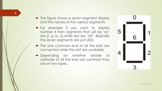
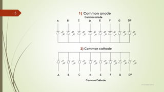
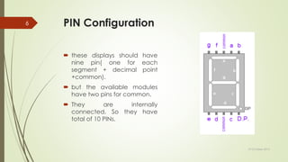
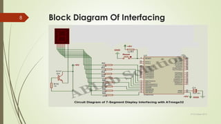
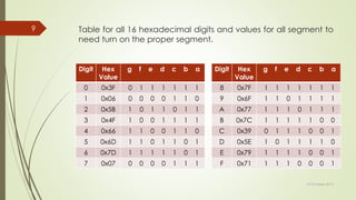
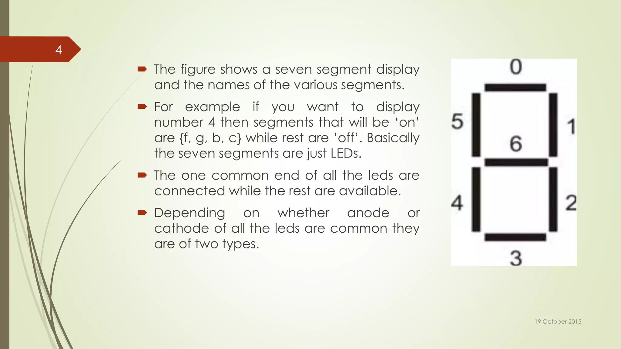
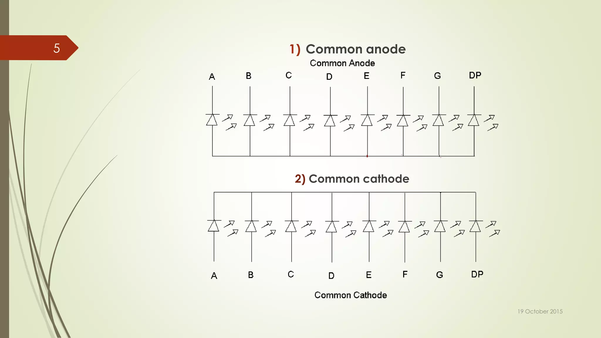
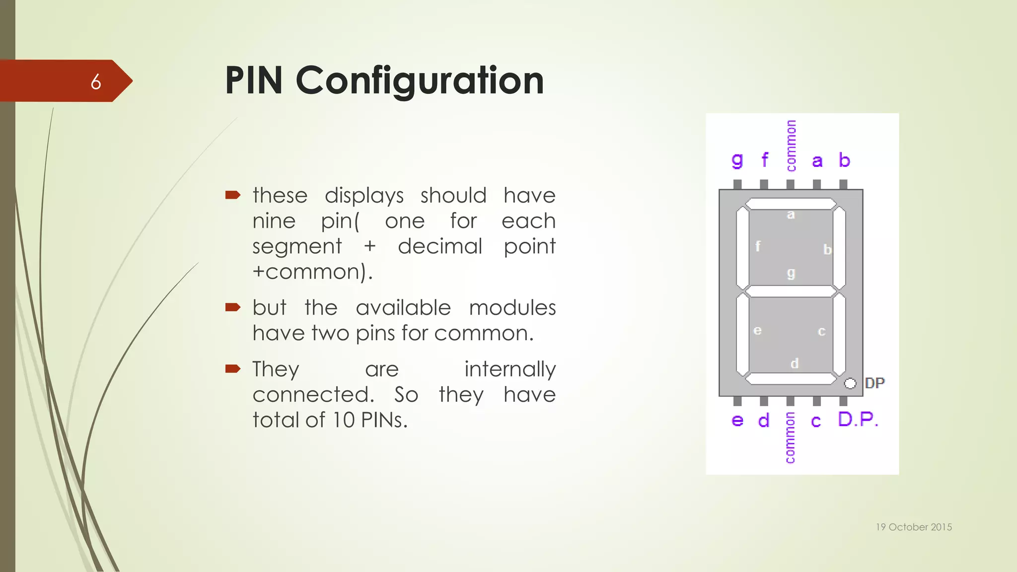
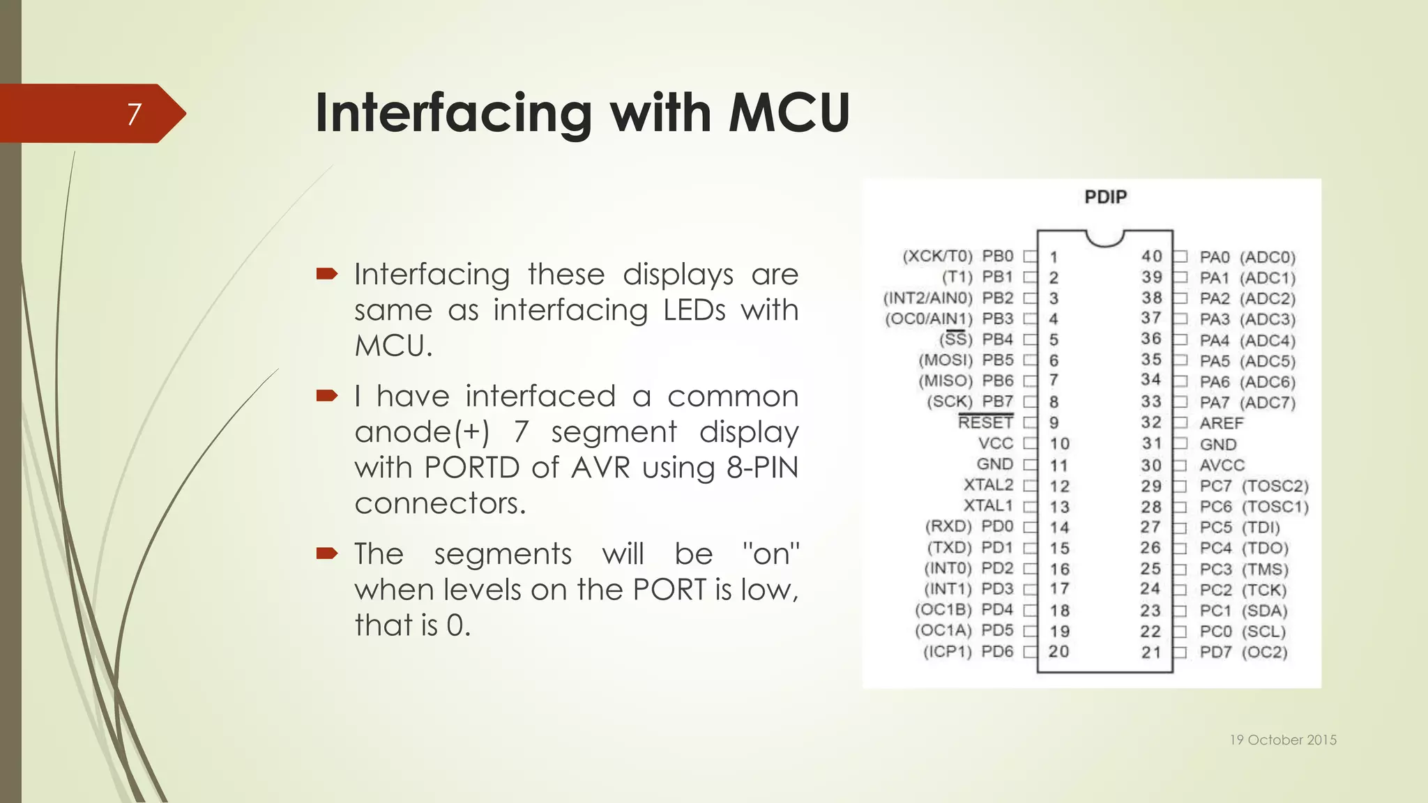
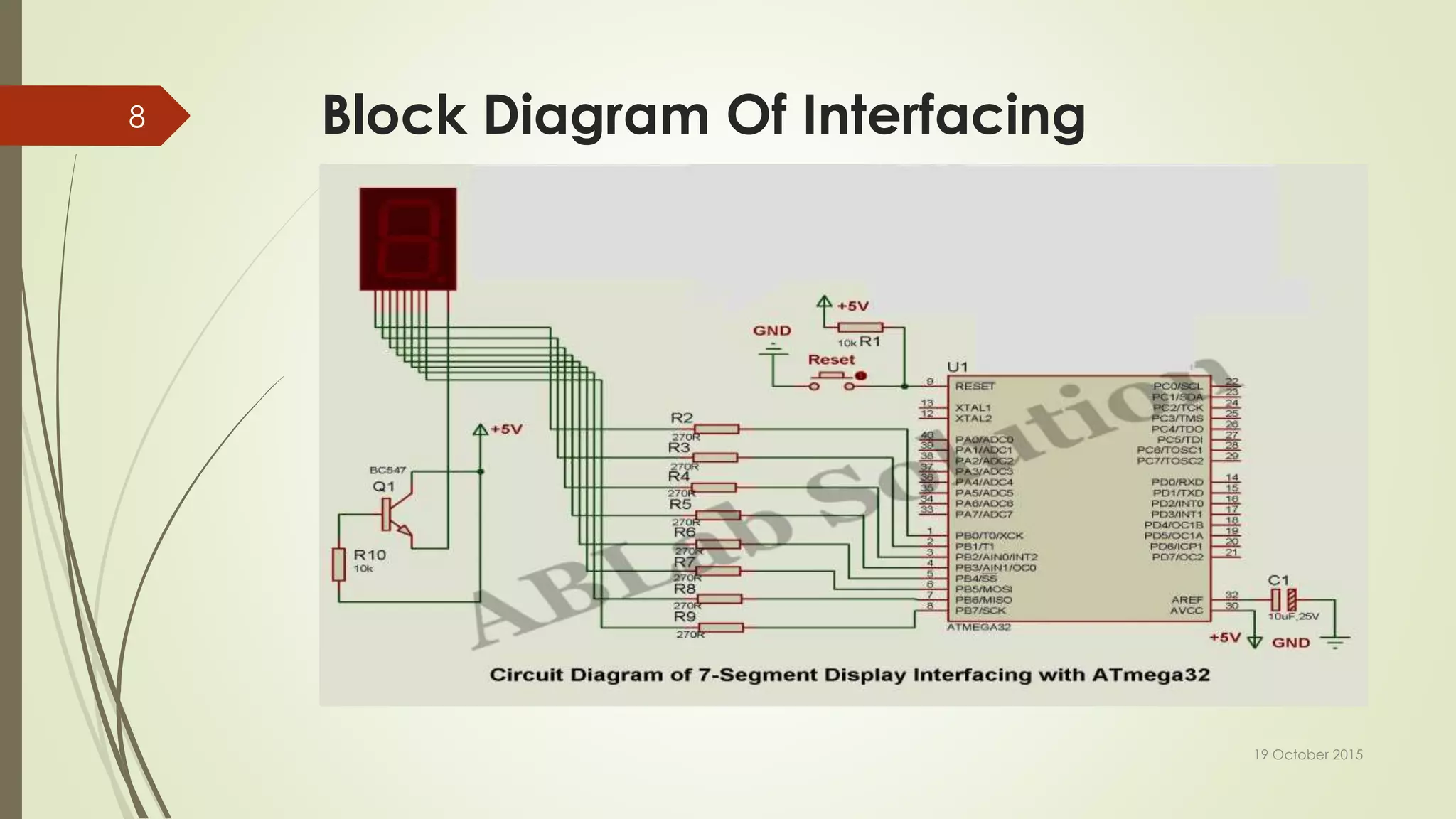
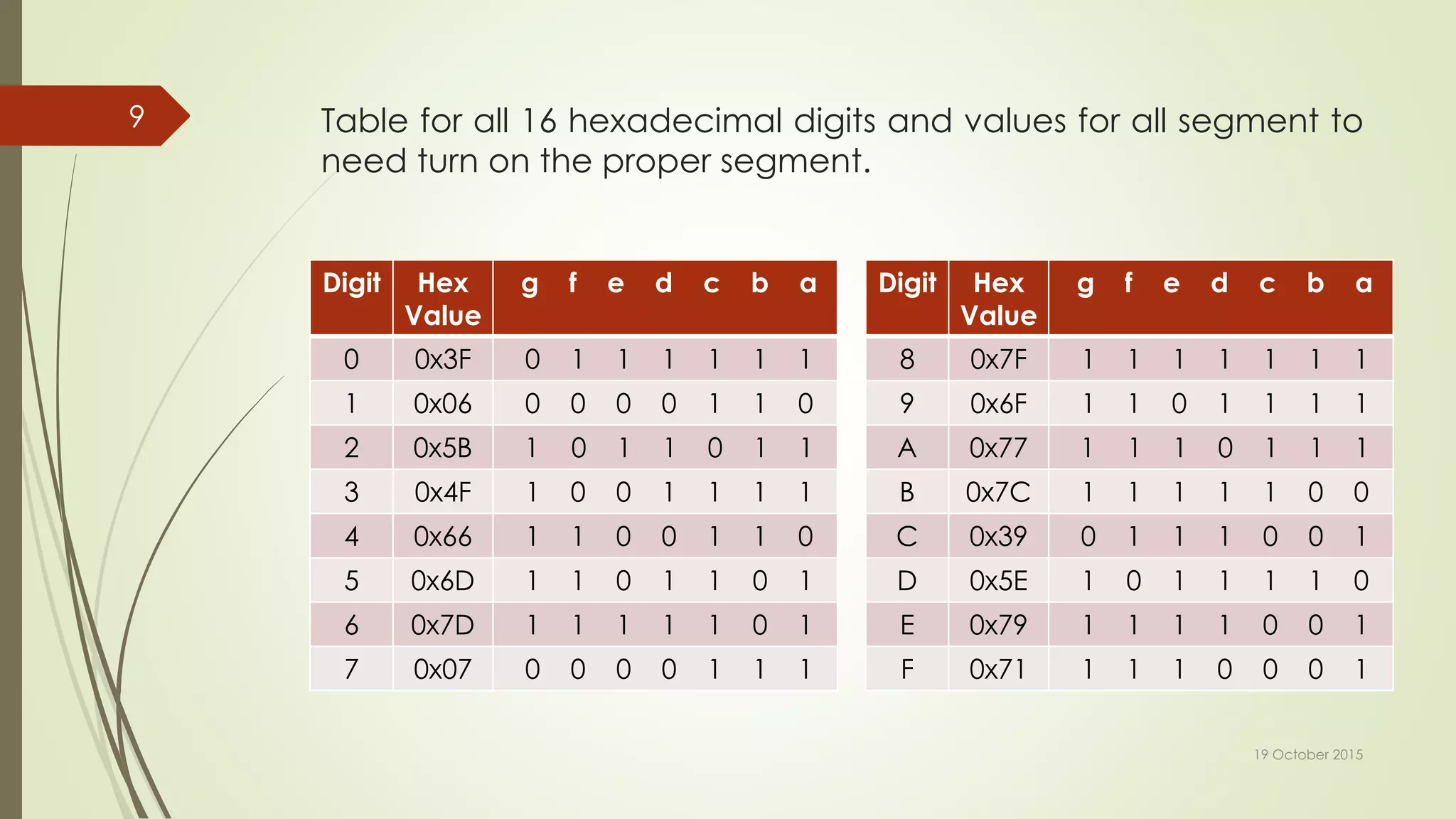
KEMBAR78
7 segment interface with avr microcontroller | PPTX
7 SEGMENT INTERFACE WITH
AVR MICROCONTROLLER
A. D. Patel Institute Of Technology
EC :- Sem V Present By :- Pratik Makadia
(130010111017)
19 October 2015
1
Introduction
 Seven segment displays are very common for electronic product to
display numerical output.
 Many common devices like calculators, watches, electronic
weighing scales, ovens etc use them.
 You must have also seen in our ADIT lifts display the current floor
numbers in seven segment displays.
19 October 2015
2
Fundamentals
 A seven-segment display is so named because it is divided into
seven different segments that can be switched on or off.
 The different combination of these segments switched on produces
different English numbers.
 The display also has a decimal point.
19 October 2015
3
 The figure shows a seven segment display
and the names of the various segments.
 For example if you want to display
number 4 then segments that will be ‘on’
are {f, g, b, c} while rest are ‘off’. Basically
the seven segments are just LEDs.
 The one common end of all the leds are
connected while the rest are available.
 Depending on whether anode or
cathode of all the leds are common they
are of two types.
19 October 2015
4
1) Common anode
19 October 2015
5
2) Common cathode
PIN Configuration
 these displays should have
nine pin( one for each
segment + decimal point
+common).
 but the available modules
have two pins for common.
 They are internally
connected. So they have
total of 10 PINs.
19 October 2015
6
Interfacing with MCU
 Interfacing these displays are
same as interfacing LEDs with
MCU.
 I have interfaced a common
anode(+) 7 segment display
with PORTD of AVR using 8-PIN
connectors.
 The segments will be "on"
when levels on the PORT is low,
that is 0.
19 October 2015
7
Block Diagram Of Interfacing
19 October 2015
8
Table for all 16 hexadecimal digits and values for all segment to
need turn on the proper segment.
Digit Hex
Value
g f e d c b a
0 0x3F 0 1 1 1 1 1 1
1 0x06 0 0 0 0 1 1 0
2 0x5B 1 0 1 1 0 1 1
3 0x4F 1 0 0 1 1 1 1
4 0x66 1 1 0 0 1 1 0
5 0x6D 1 1 0 1 1 0 1
6 0x7D 1 1 1 1 1 0 1
7 0x07 0 0 0 0 1 1 1
19 October 2015
9
Digit Hex
Value
g f e d c b a
8 0x7F 1 1 1 1 1 1 1
9 0x6F 1 1 0 1 1 1 1
A 0x77 1 1 1 0 1 1 1
B 0x7C 1 1 1 1 1 0 0
C 0x39 0 1 1 1 0 0 1
D 0x5E 1 0 1 1 1 1 0
E 0x79 1 1 1 1 0 0 1
F 0x71 1 1 1 0 0 0 1
Programming
 These displays are very easy to program in C.
 The controller is initialized by sending three commands:
1) Turning on its internal oscillator
2) Enabling display output
3) Setting the brightness level
 Brightness is adjusted from 0 (dimmest) to 15 (brightest).
19 October 2015
10
19 October 2015
11

7 segment interface with avr microcontroller

  • 1.
    7 SEGMENT INTERFACEWITH AVR MICROCONTROLLER A. D. Patel Institute Of Technology EC :- Sem V Present By :- Pratik Makadia (130010111017) 19 October 2015 1
  • 2.
    Introduction  Seven segmentdisplays are very common for electronic product to display numerical output.  Many common devices like calculators, watches, electronic weighing scales, ovens etc use them.  You must have also seen in our ADIT lifts display the current floor numbers in seven segment displays. 19 October 2015 2
  • 3.
    Fundamentals  A seven-segmentdisplay is so named because it is divided into seven different segments that can be switched on or off.  The different combination of these segments switched on produces different English numbers.  The display also has a decimal point. 19 October 2015 3
  • 4.
     The figureshows a seven segment display and the names of the various segments.  For example if you want to display number 4 then segments that will be ‘on’ are {f, g, b, c} while rest are ‘off’. Basically the seven segments are just LEDs.  The one common end of all the leds are connected while the rest are available.  Depending on whether anode or cathode of all the leds are common they are of two types. 19 October 2015 4
  • 5.
    1) Common anode 19October 2015 5 2) Common cathode
  • 6.
    PIN Configuration  thesedisplays should have nine pin( one for each segment + decimal point +common).  but the available modules have two pins for common.  They are internally connected. So they have total of 10 PINs. 19 October 2015 6
  • 7.
    Interfacing with MCU Interfacing these displays are same as interfacing LEDs with MCU.  I have interfaced a common anode(+) 7 segment display with PORTD of AVR using 8-PIN connectors.  The segments will be "on" when levels on the PORT is low, that is 0. 19 October 2015 7
  • 8.
    Block Diagram OfInterfacing 19 October 2015 8
  • 9.
    Table for all16 hexadecimal digits and values for all segment to need turn on the proper segment. Digit Hex Value g f e d c b a 0 0x3F 0 1 1 1 1 1 1 1 0x06 0 0 0 0 1 1 0 2 0x5B 1 0 1 1 0 1 1 3 0x4F 1 0 0 1 1 1 1 4 0x66 1 1 0 0 1 1 0 5 0x6D 1 1 0 1 1 0 1 6 0x7D 1 1 1 1 1 0 1 7 0x07 0 0 0 0 1 1 1 19 October 2015 9 Digit Hex Value g f e d c b a 8 0x7F 1 1 1 1 1 1 1 9 0x6F 1 1 0 1 1 1 1 A 0x77 1 1 1 0 1 1 1 B 0x7C 1 1 1 1 1 0 0 C 0x39 0 1 1 1 0 0 1 D 0x5E 1 0 1 1 1 1 0 E 0x79 1 1 1 1 0 0 1 F 0x71 1 1 1 0 0 0 1
  • 10.
    Programming  These displaysare very easy to program in C.  The controller is initialized by sending three commands: 1) Turning on its internal oscillator 2) Enabling display output 3) Setting the brightness level  Brightness is adjusted from 0 (dimmest) to 15 (brightest). 19 October 2015 10
  • 11.