Download as PPSX, PPTX


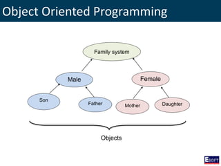

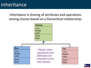


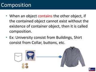


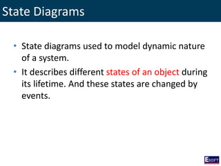
![State Diagrams
Vacancy Opened Updated Vacancy
Closed
/ Create / Update
[isOpen] / Close
Deleted
/ Delete
/ Delete](https://image.slidesharecdn.com/moduleiii-161114071916/85/DISE-OOAD-Using-UML-44-320.jpg)
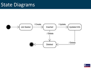


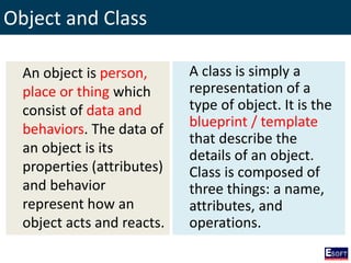
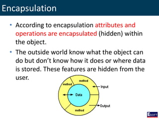
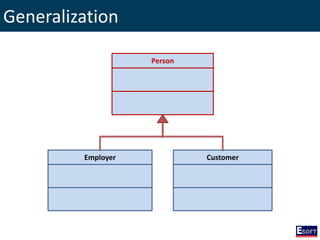
![State Diagrams
Vacancy Opened Updated Vacancy
Closed
/ Create / Update
[isOpen] / Close
Deleted
/ Delete
/ Delete](https://image.slidesharecdn.com/moduleiii-161114071916/75/DISE-OOAD-Using-UML-44-2048.jpg)


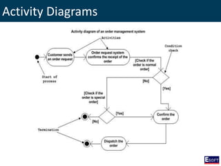
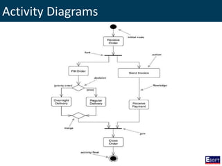
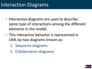
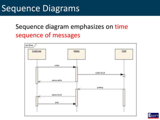
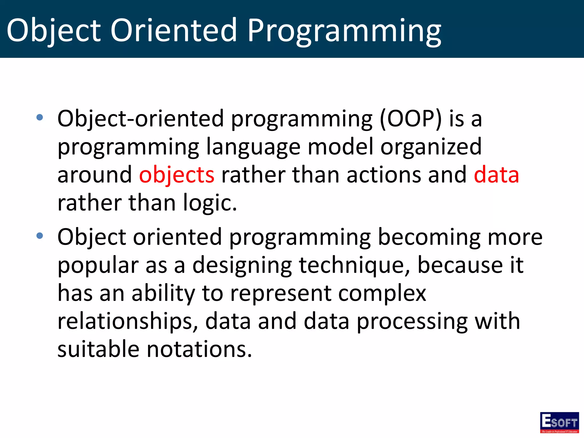
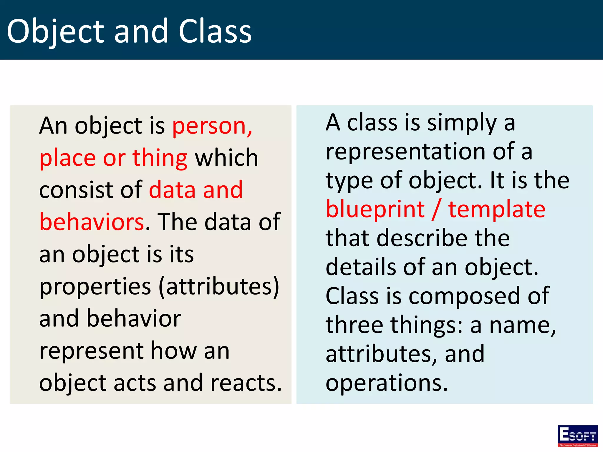
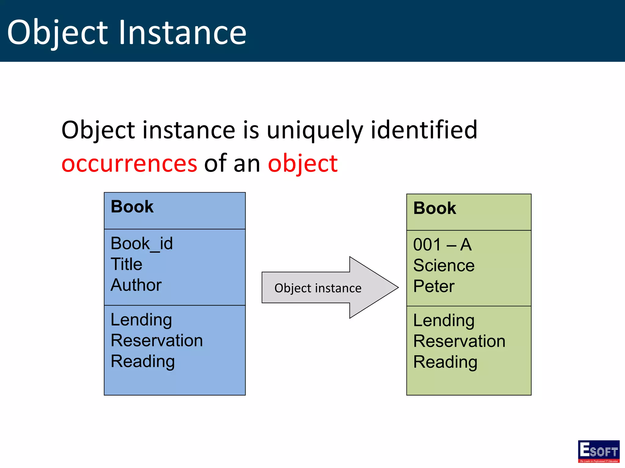
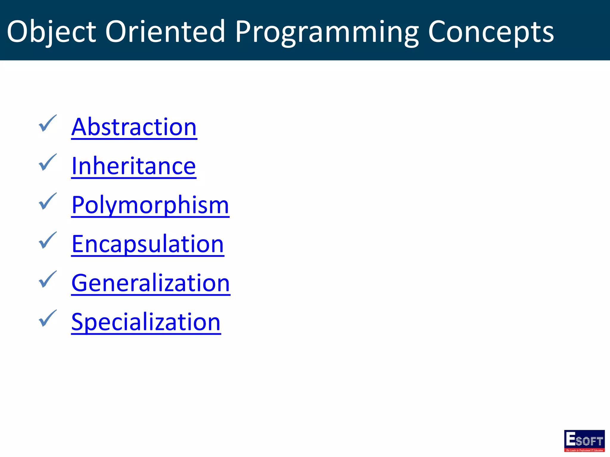
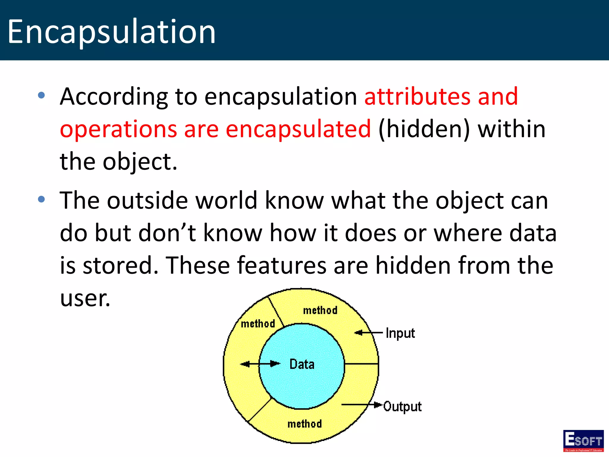
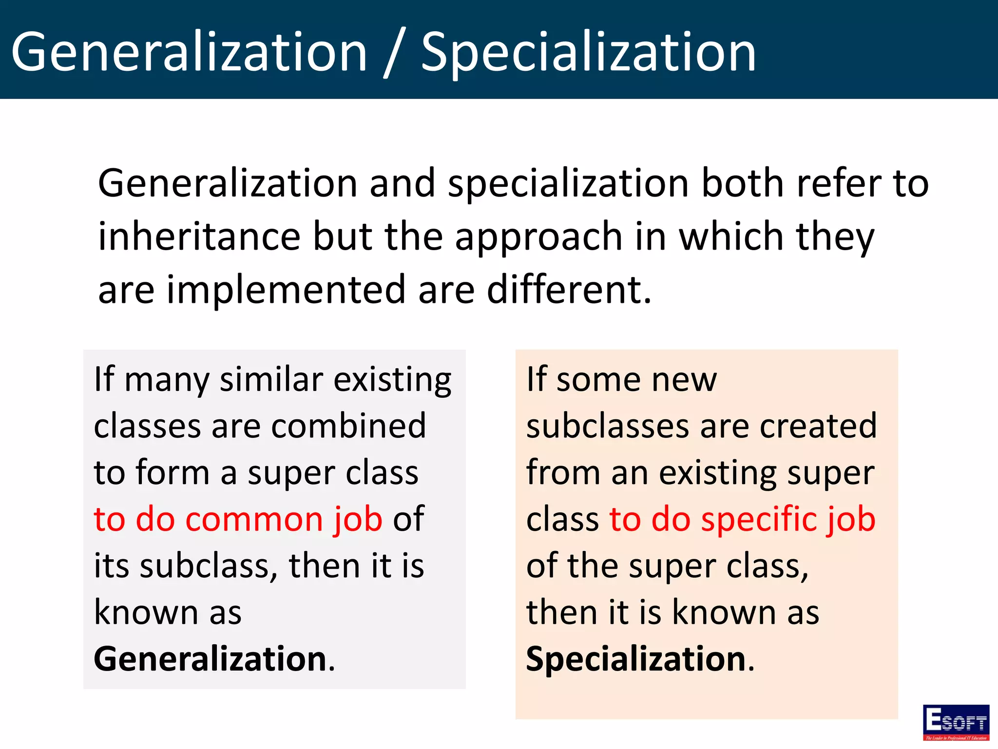
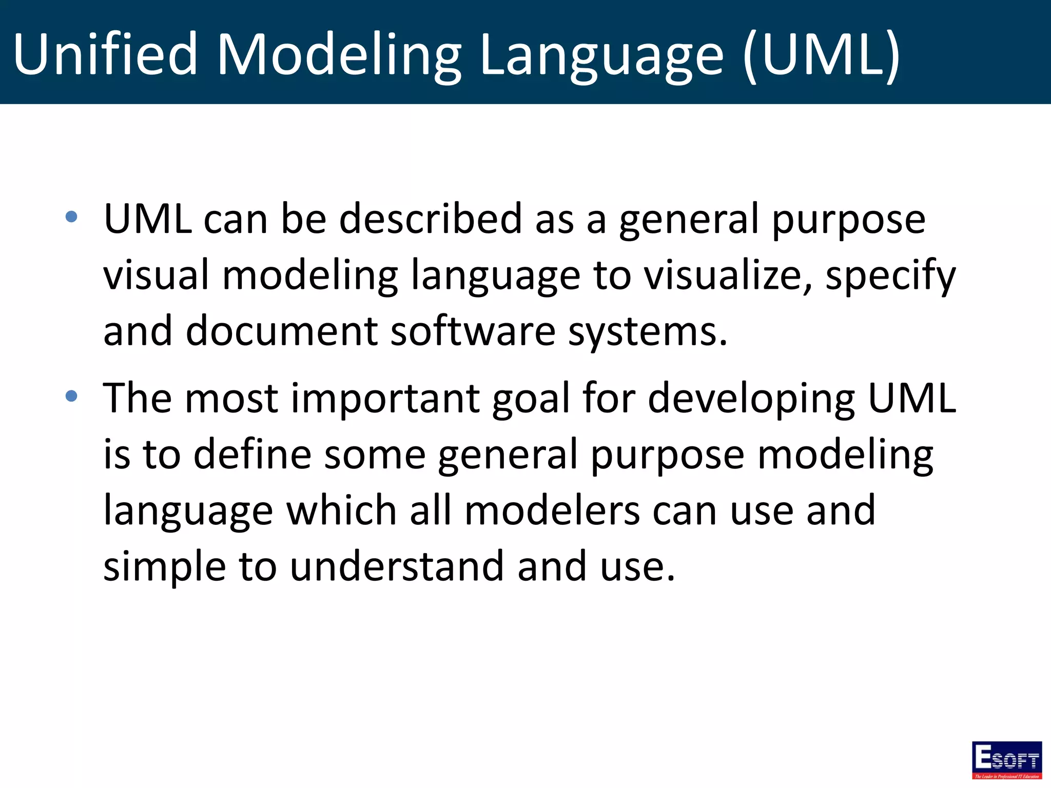
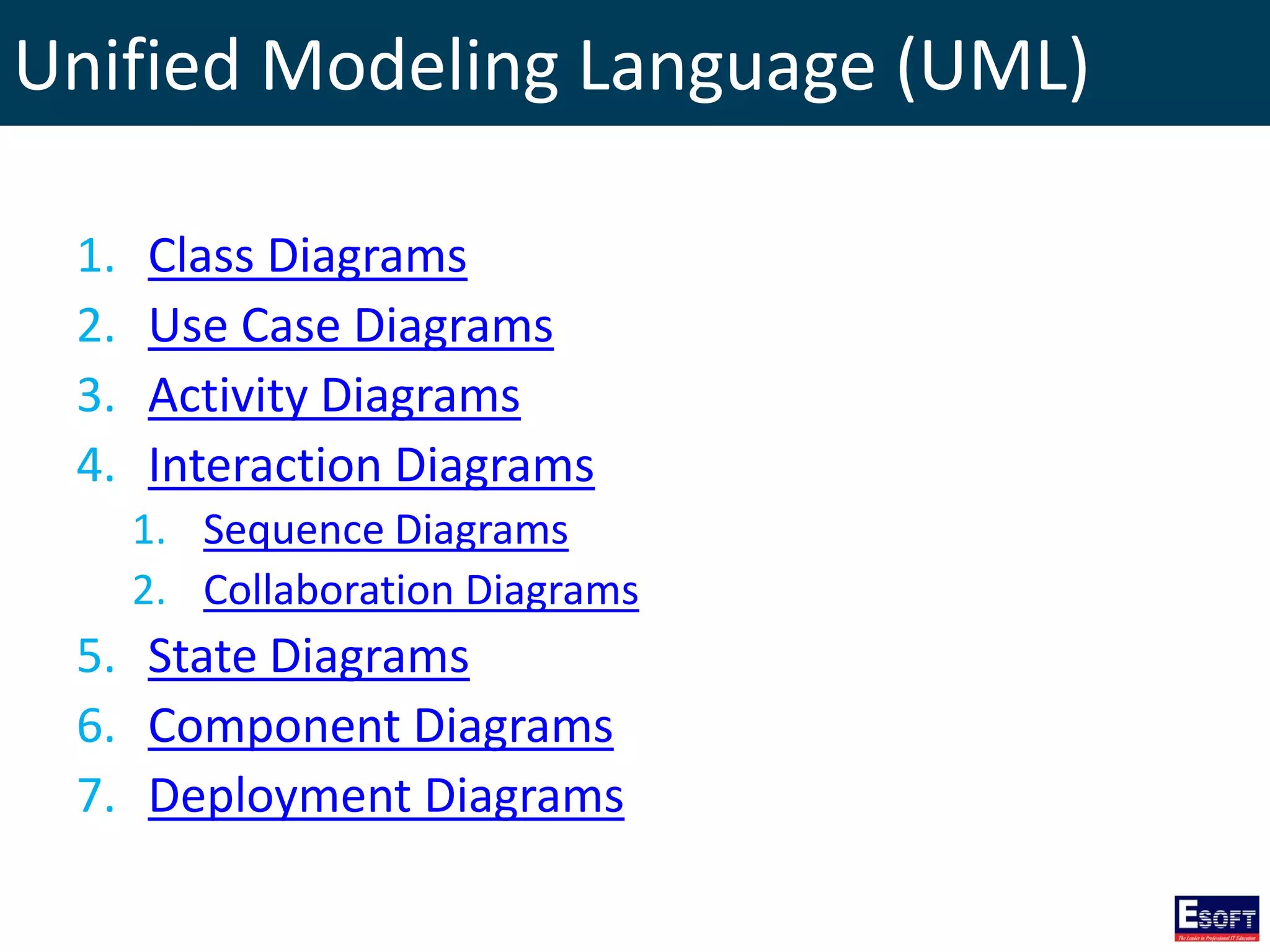
The document outlines a diploma program in software engineering focusing on Object-Oriented Analysis and Design (OOAD) using UML. It covers essential concepts such as object-oriented programming principles, UML diagrams like class, use case, activity, and interaction diagrams, and various other modeling techniques. The curriculum aims to equip learners with the skills to visualize and document software systems effectively.


