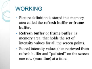
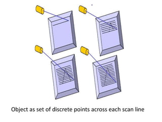
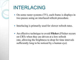
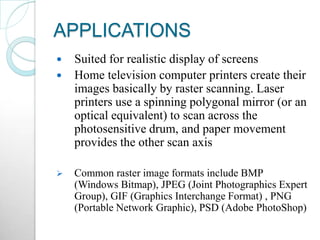
Downloaded 3,946 times
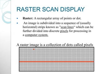

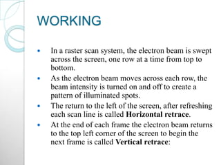
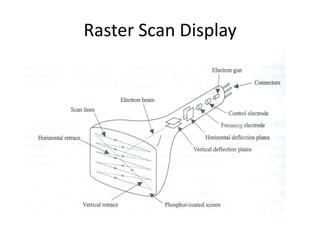


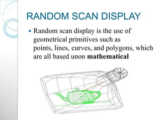


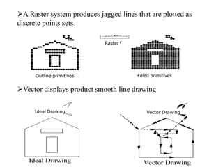
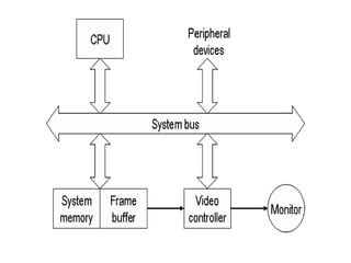
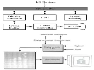
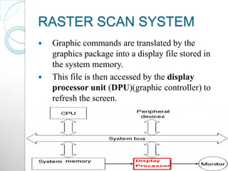
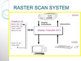

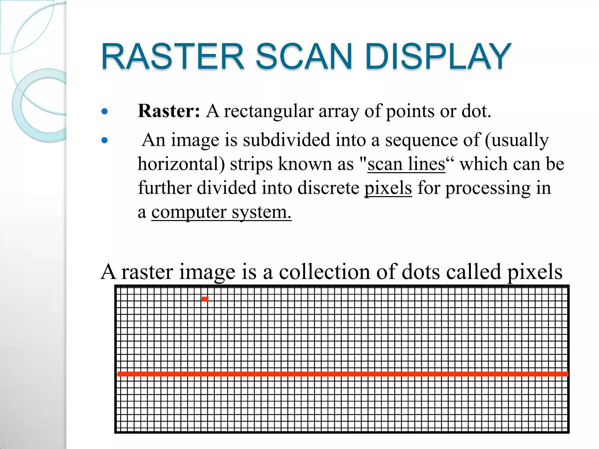

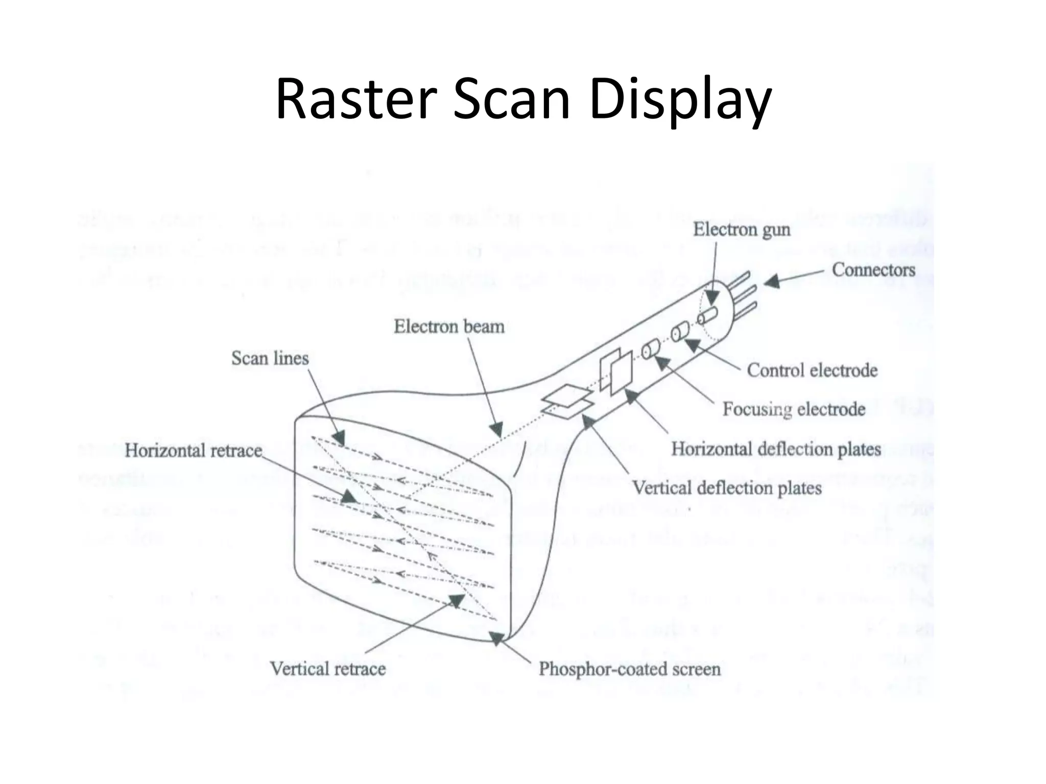
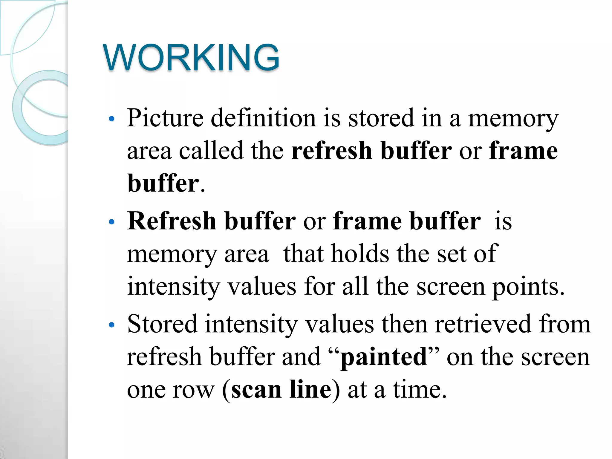

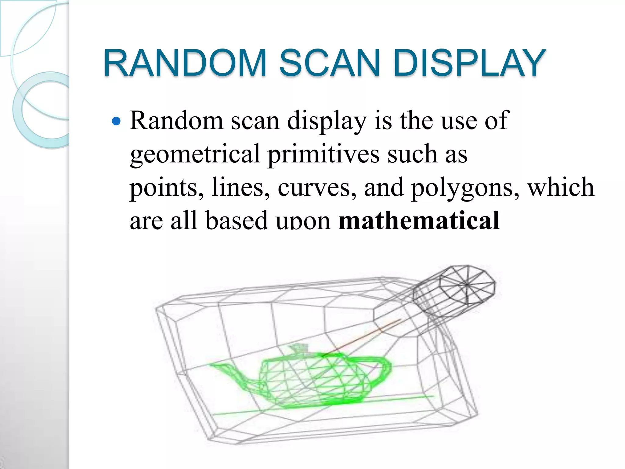
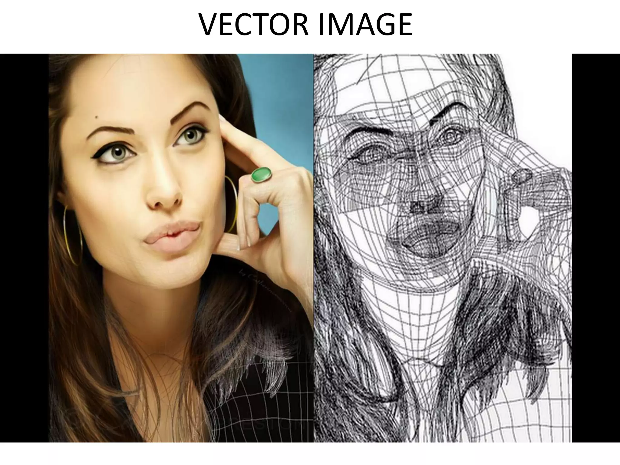
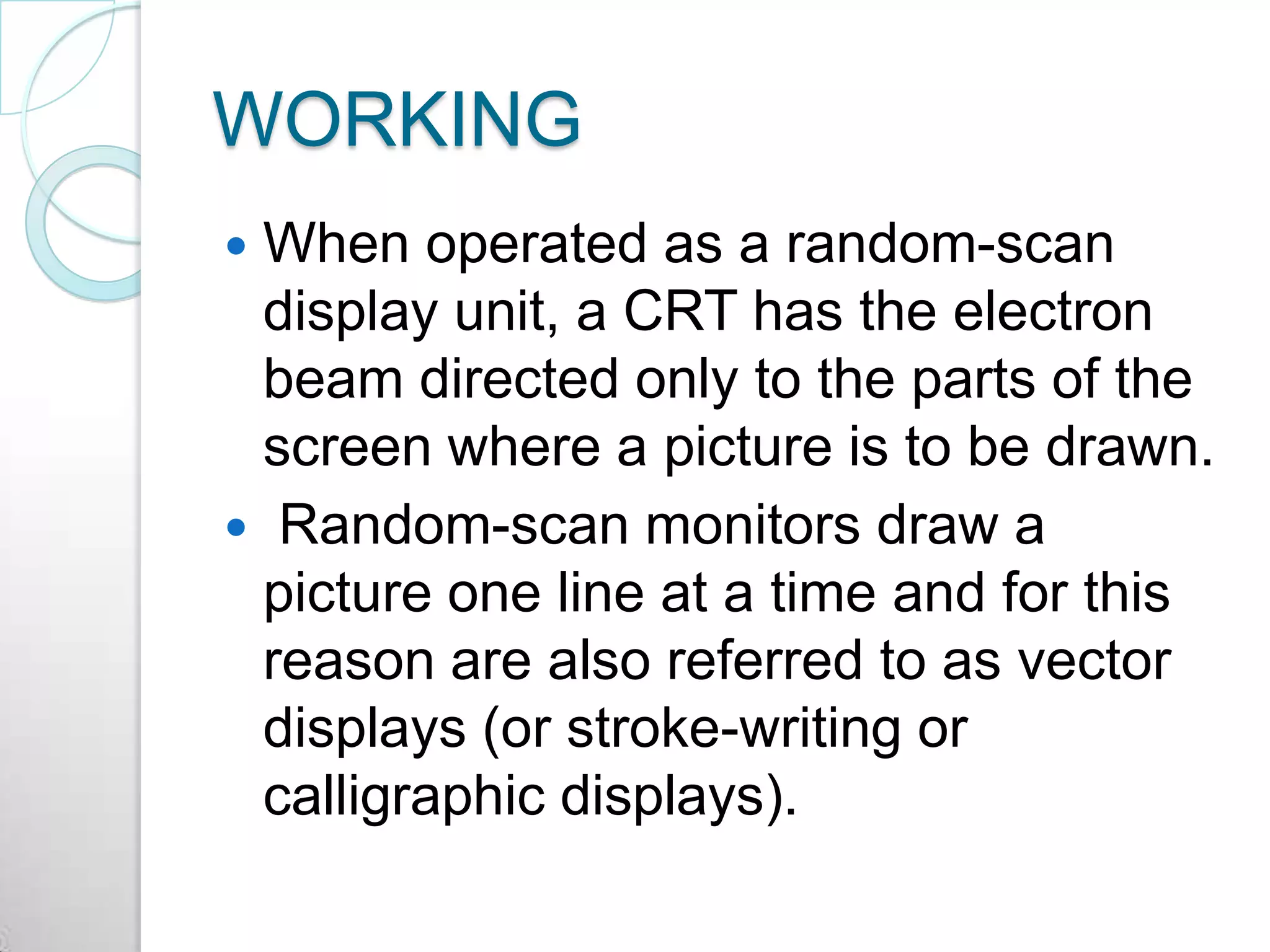
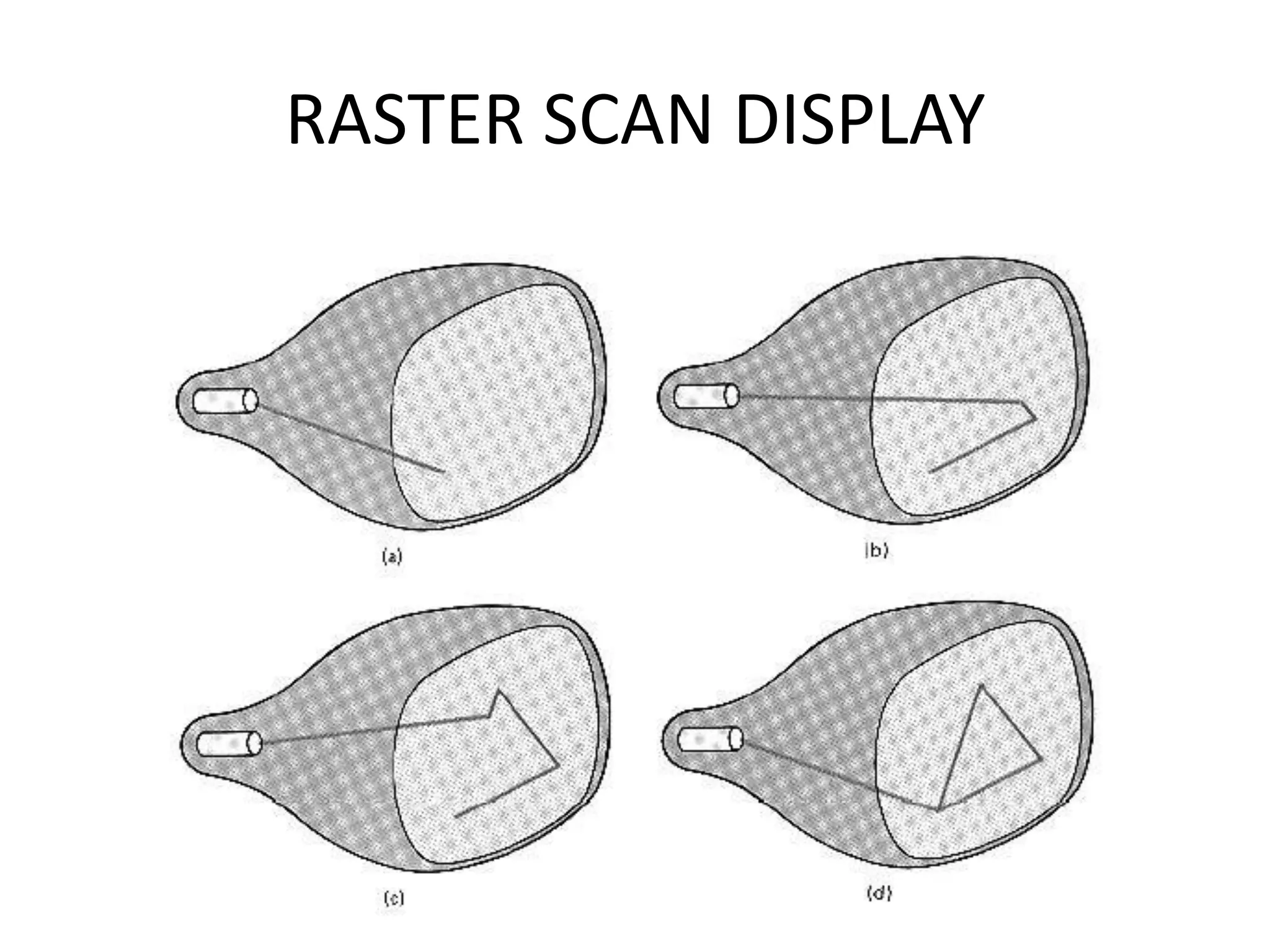


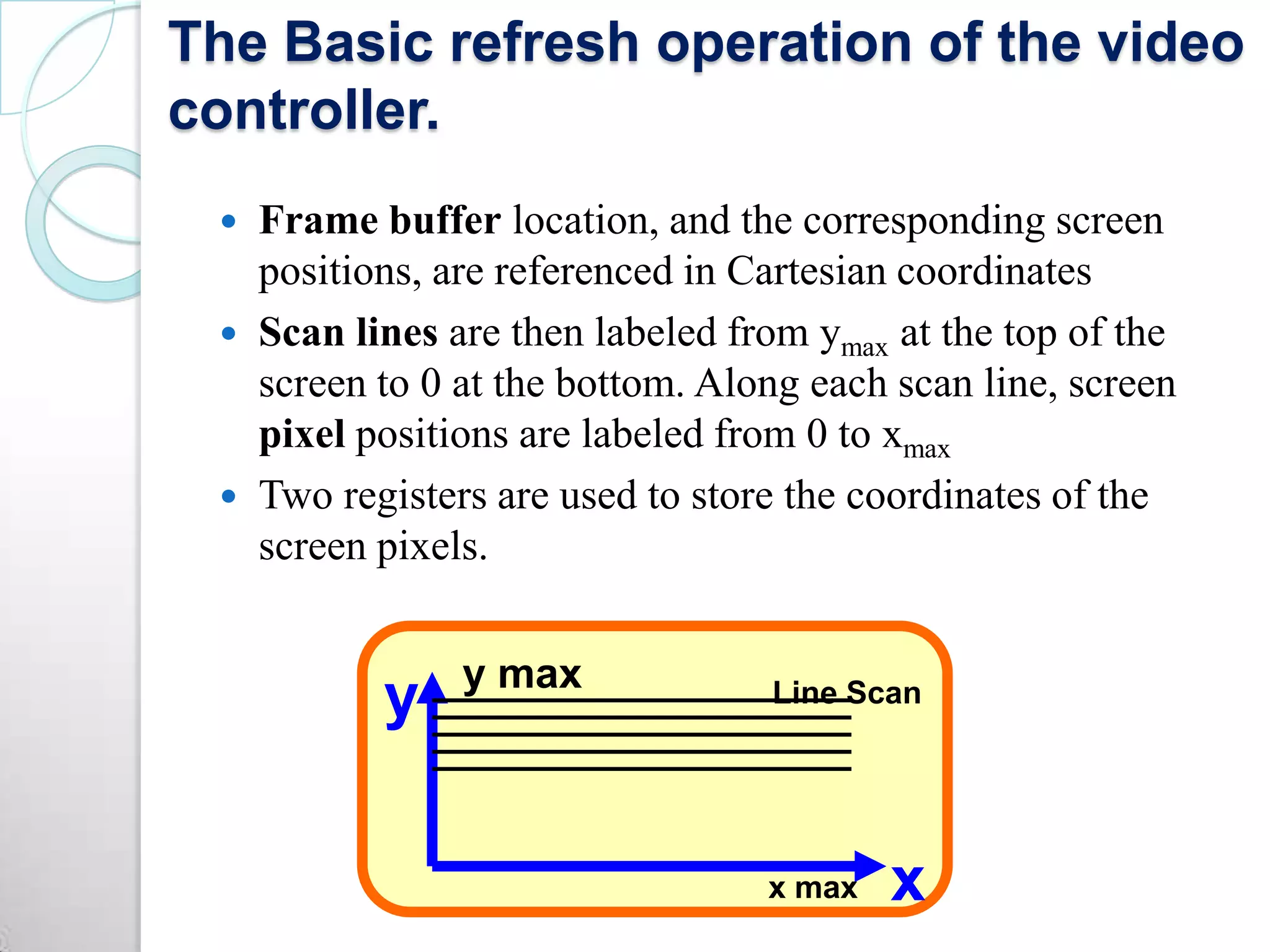
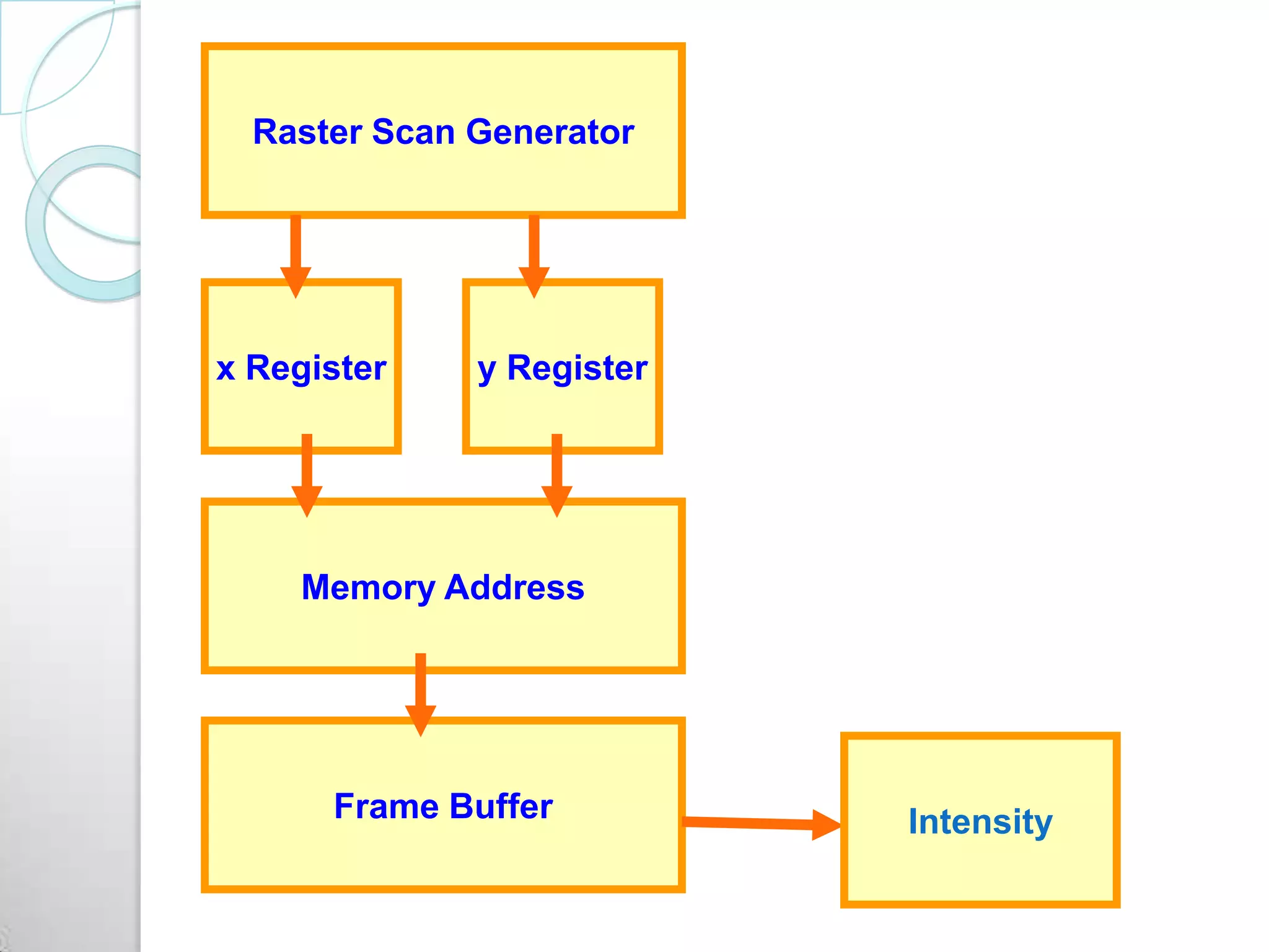
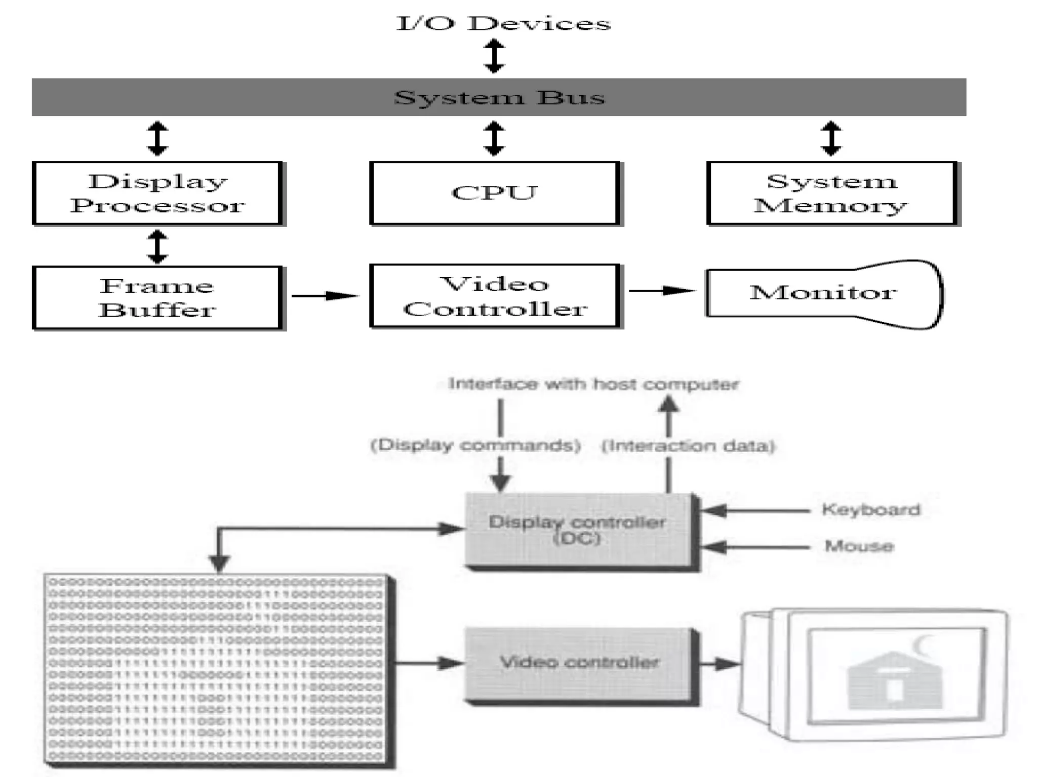


Raster scan displays work by sweeping an electron beam across the screen in horizontal lines from top to bottom. As the beam moves, its intensity is turned on and off to illuminate pixels and form an image. The pixel values are stored in and retrieved from a refresh buffer or frame buffer. Random scan displays draw images using geometric primitives like points and lines based on mathematical equations, directing the electron beam only where needed. Raster scans have higher resolution but jagged lines, while random scans produce smooth lines but cannot display complex images. Both use a video controller and frame buffer in memory to control the display process.


