The document introduces Arduino pins and their functions. It describes the different types of signals and then discusses the ATmega328p microcontroller used in Arduino boards. It details the various pin types on Arduino boards including power pins, analog input pins, digital I/O pins, Tx/Rx pins for serial communication, and special function pins. The pin functions described include power regulation, analog to digital conversion, digital input/output, serial data transmission/reception, and resetting the microcontroller.
Signal
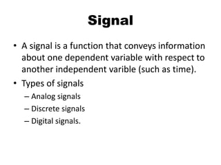
• A signalis a function that conveys information
about one dependent variable with respect to
another independent varible (such as time).
• Types of signals
– Analog signals
– Discrete signals
– Digital signals.
3.
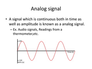
Analog signal
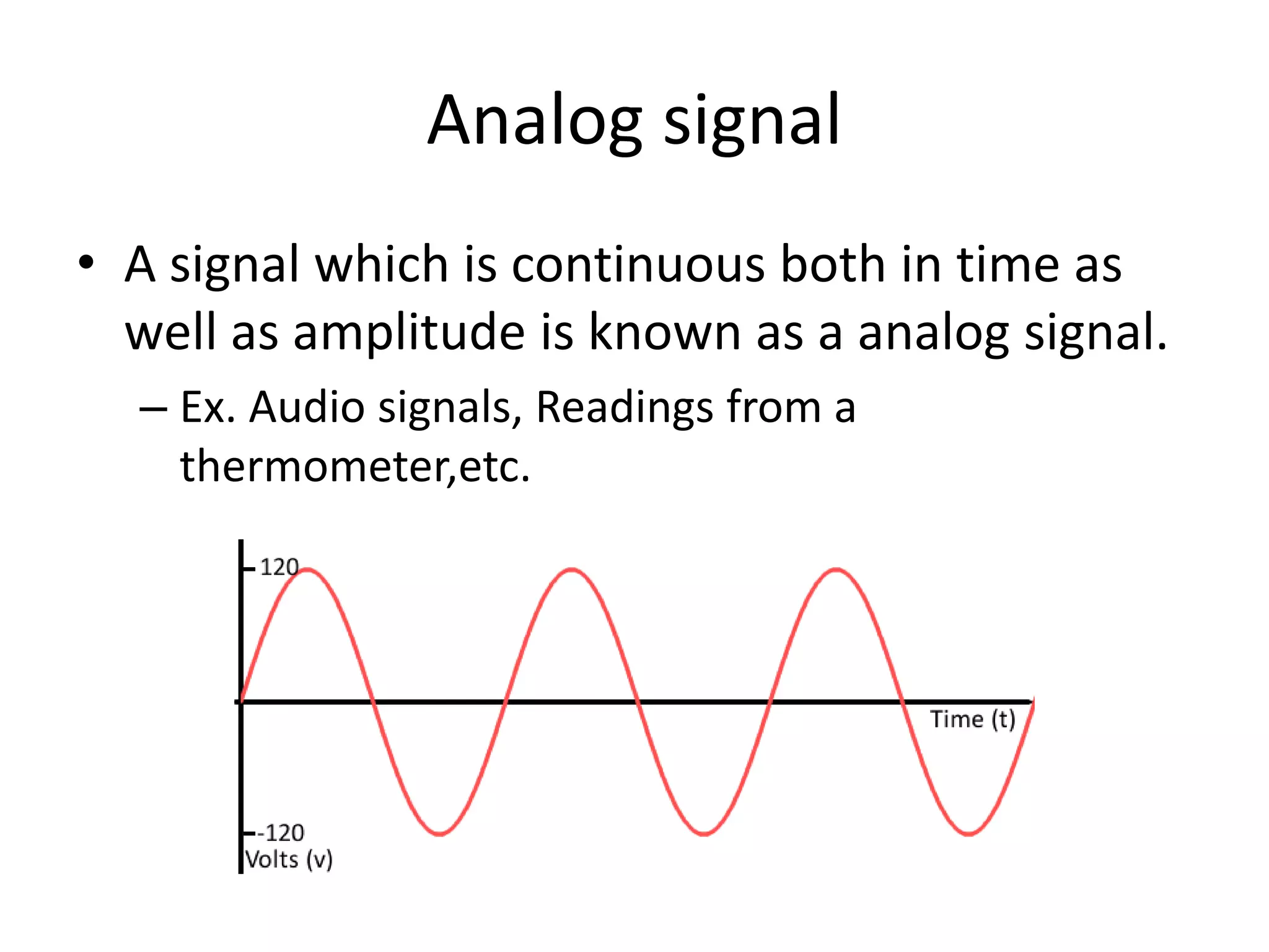
• Asignal which is continuous both in time as
well as amplitude is known as a analog signal.
– Ex. Audio signals, Readings from a
thermometer,etc.
4.
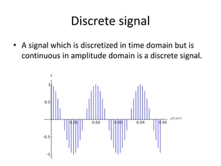
Discrete signal
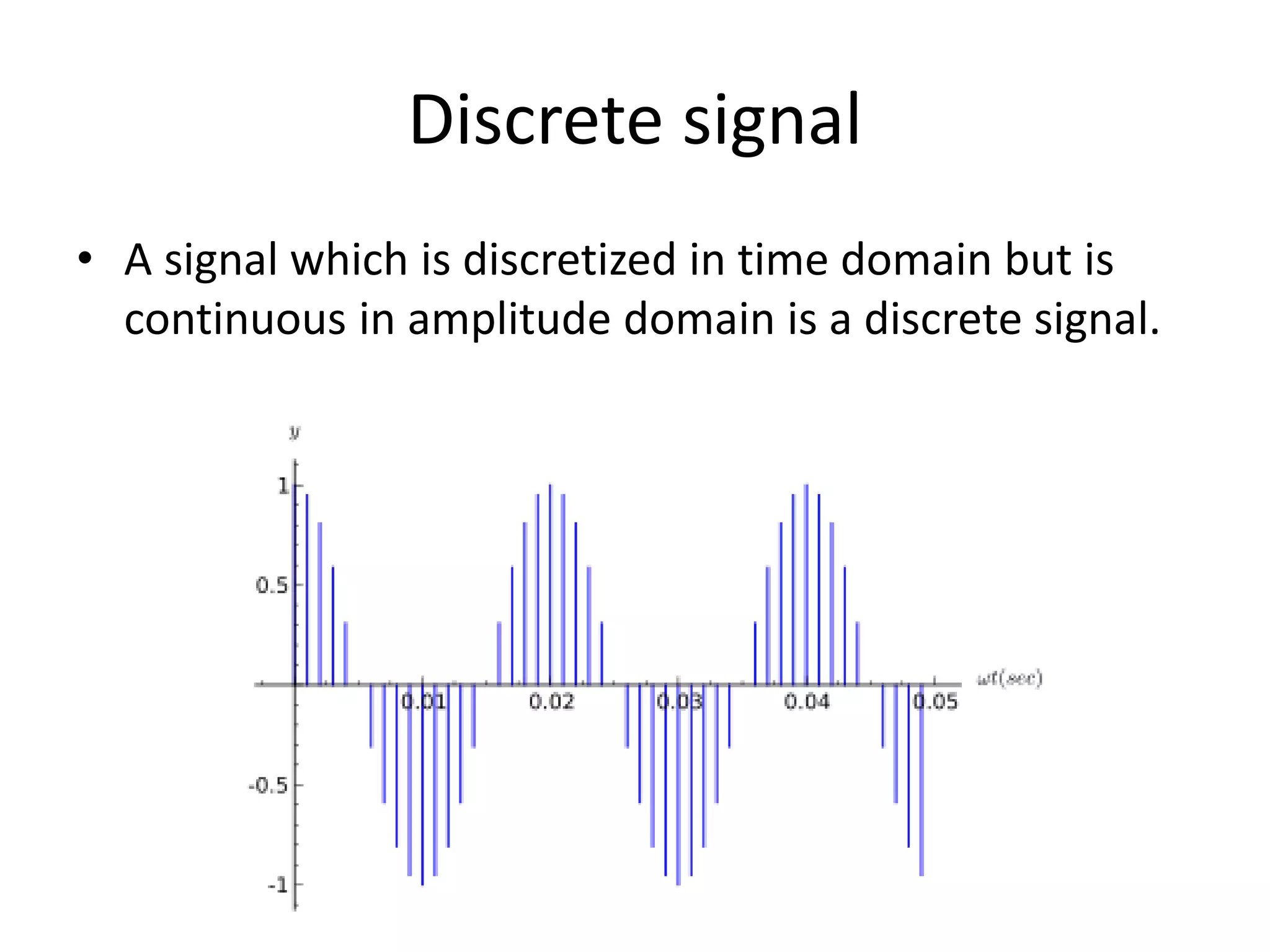
• Asignal which is discretized in time domain but is
continuous in amplitude domain is a discrete signal.
5.
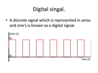
Digital singal.
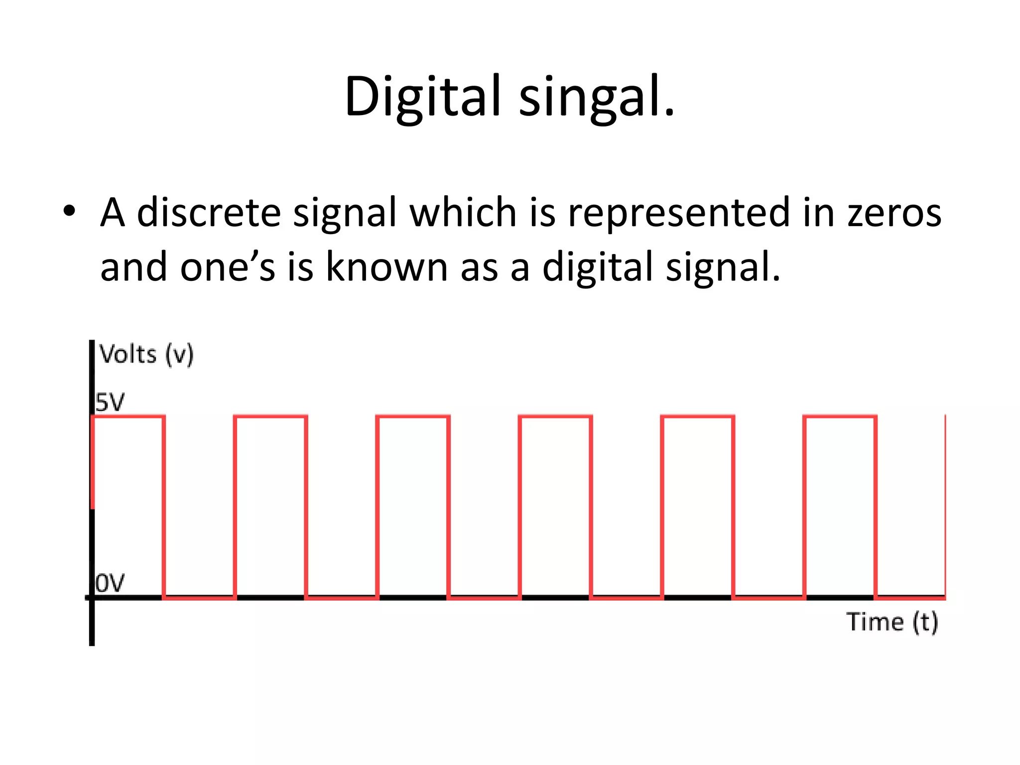
• Adiscrete signal which is represented in zeros
and one’s is known as a digital signal.
6.
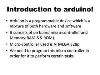
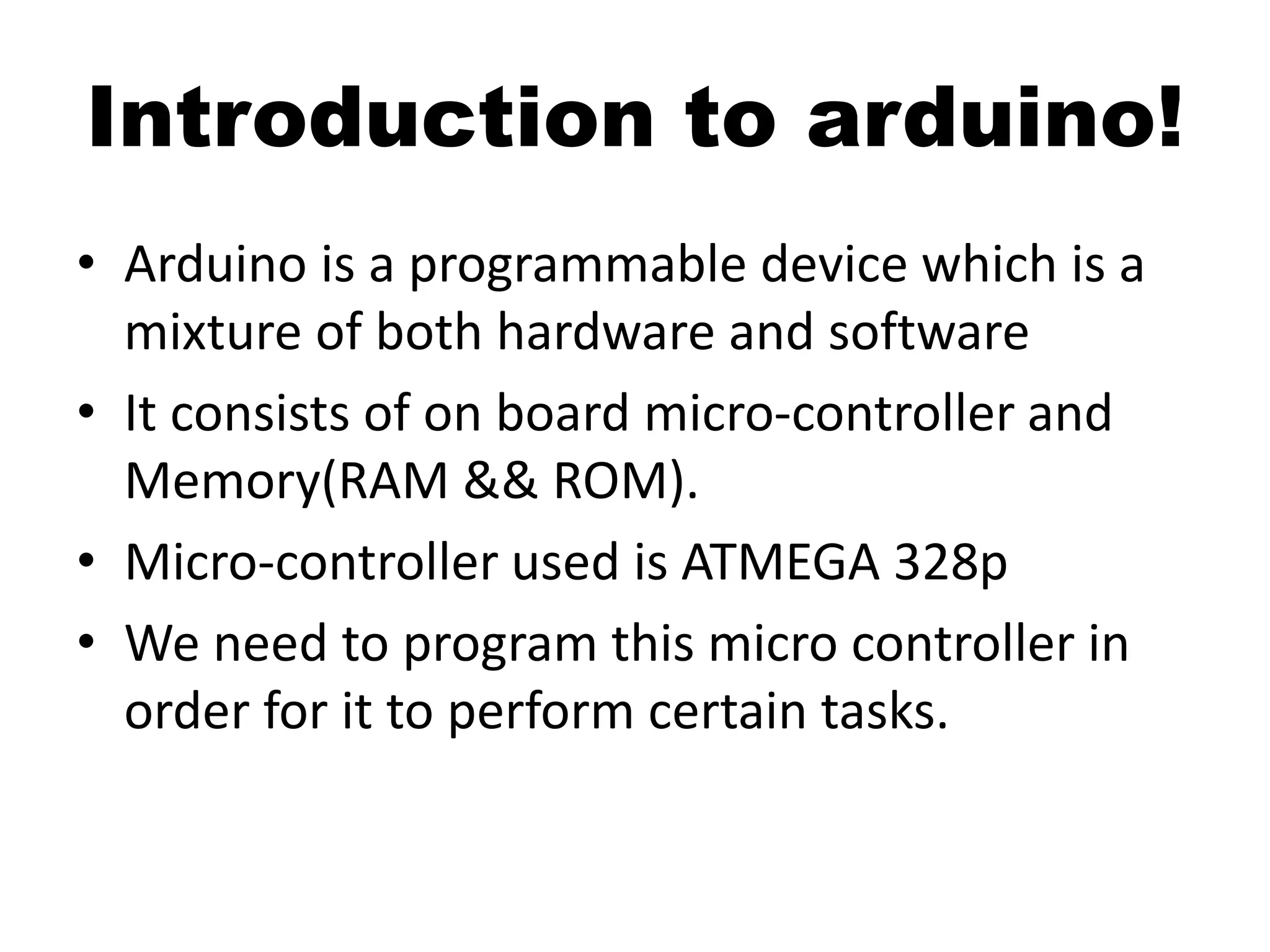
Introduction to arduino!
•Arduino is a programmable device which is a
mixture of both hardware and software
• It consists of on board micro-controller and
Memory(RAM && ROM).
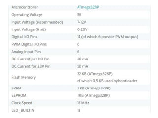
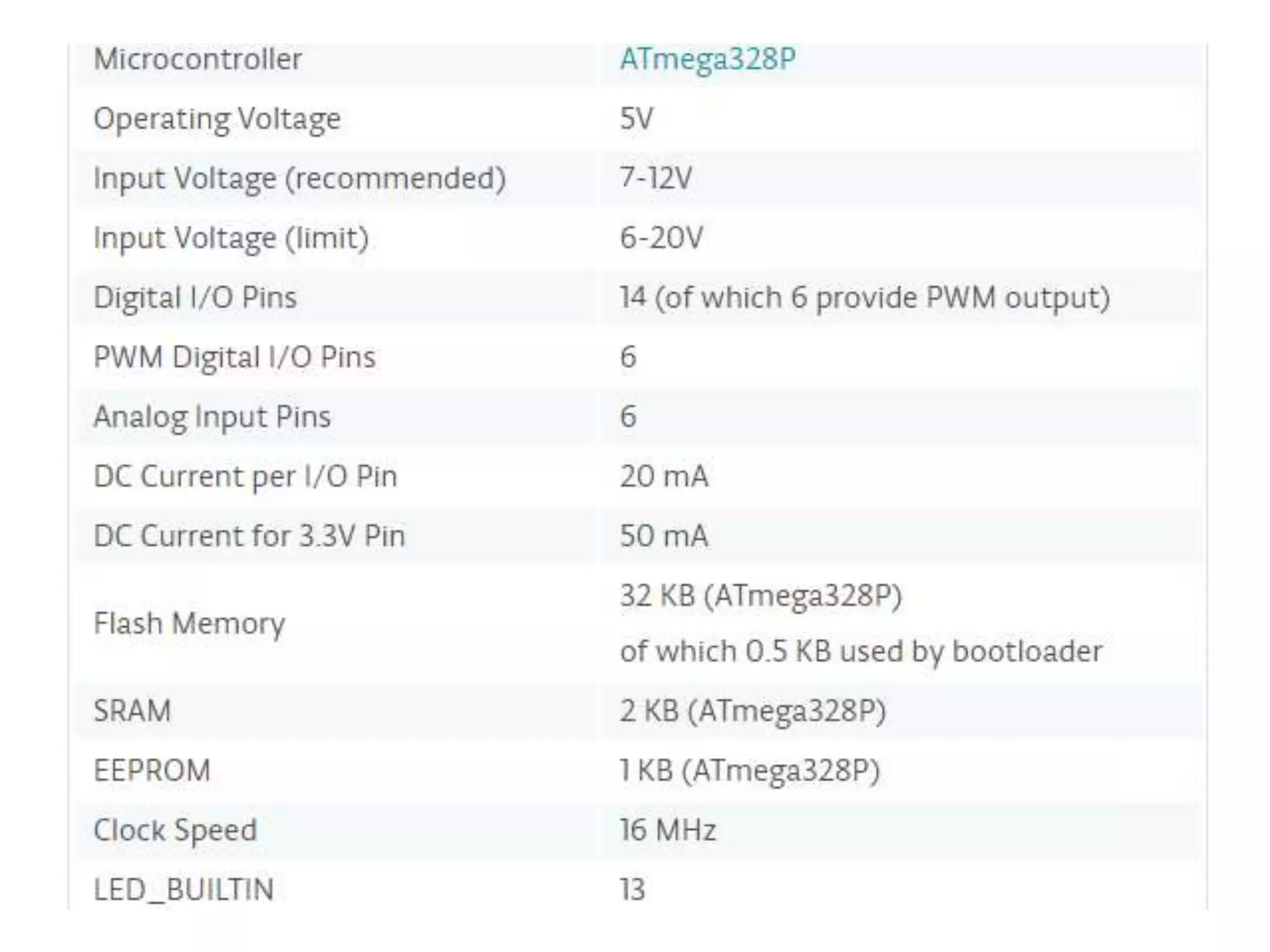
• Micro-controller used is ATMEGA 328p
• We need to program this micro controller in
order for it to perform certain tasks.
7.
• A micro-controllerunderstands only one’s and
zeros, so we will have to write programs in
high level language such as C and compile
them into machine level language.
• This program is then uploaded into the board
for it to perform the required task
• This programming is done using Arduino IDE.
• A micro-controller has i/o ports and memory
• The programs and data which are to be sent
are stored in the memory.
• Then data is transferred via the I/O ports
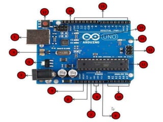
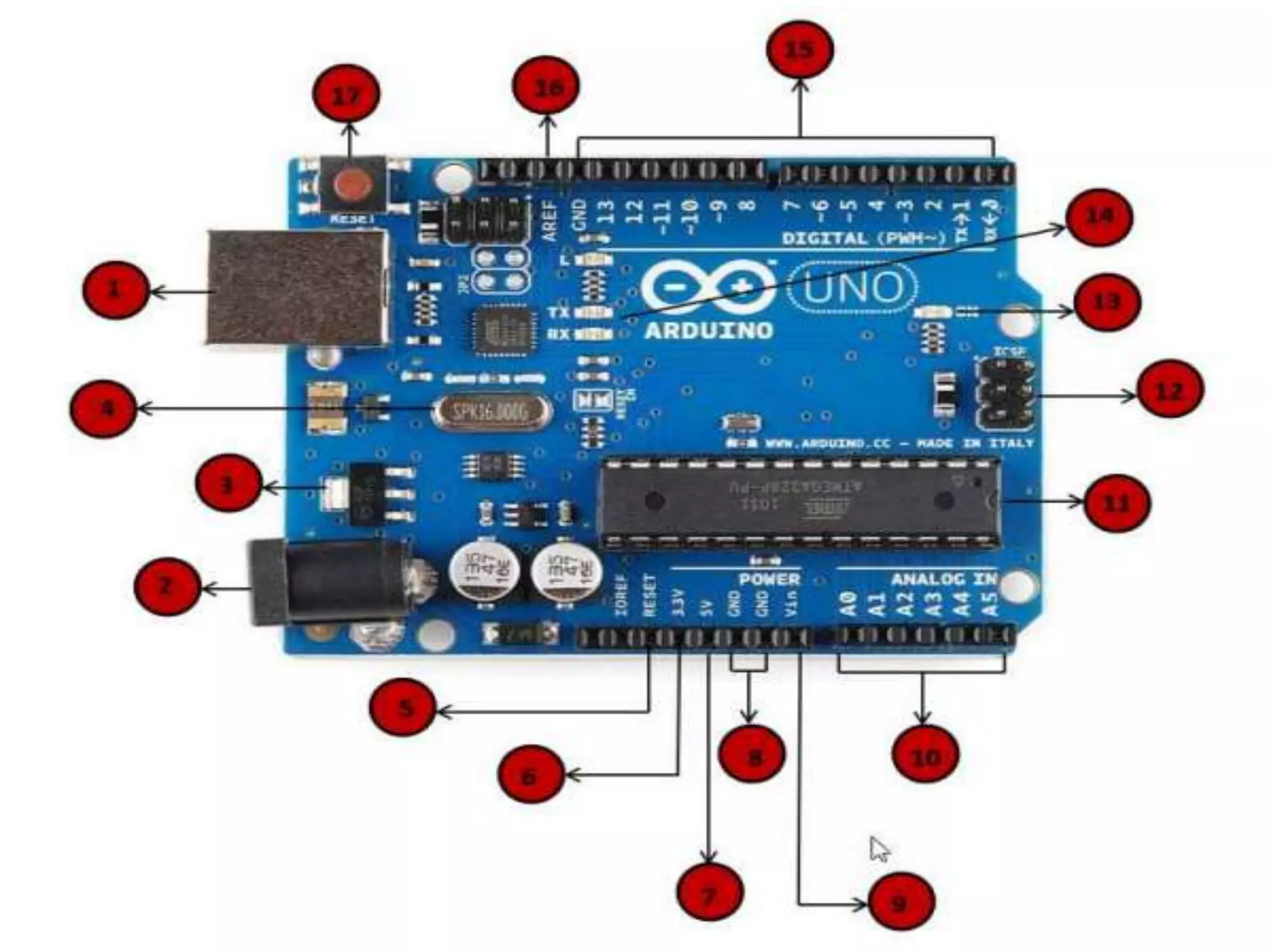
PIN LAYOUT OFARDUINO
• Power pins
• Your arduino requires power to run!
• Power can be given to the arduino in 3 ways:
– Using a Battery to coaxial connector.
– Using a USB from a laptop
– Using the Vin ports of the arduino(Should’nt
exceed 7-12v).
12.
• The functionof the voltage regulator is to
control the voltage given to the Arduino
board and stabilize the DC voltages used by
the processor and other elements.
Voltage regulator
14.
Power Output pins
•5v – Gives 5v output at maximum current of
~400 MA.
• 3.3v- Gives 3.3V output at a maximum current
of 150 MA.
• GND : It is taken as the reference point for all
the voltages measured ie. Any voltage
measured is compared to the voltage at this
terminal.
16.
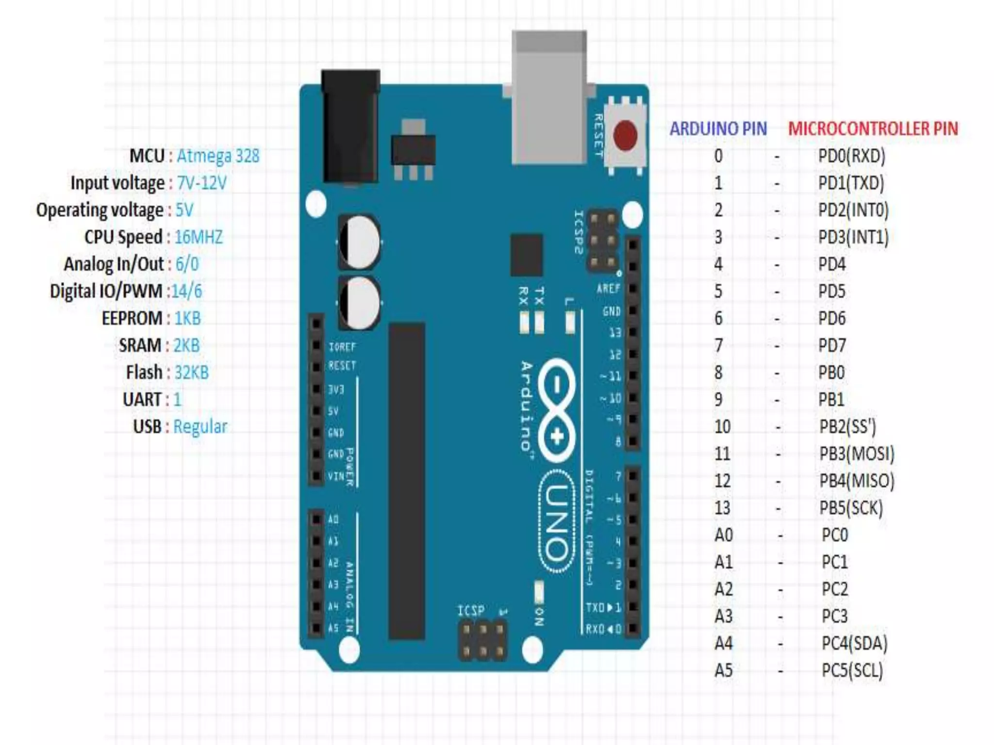
Analog pins(input)
• TheArduino UNO board has five analog input
pins A0 through A5. These pins can read the
signal from an analog sensor like the humidity
sensor or temperature sensor and convert it
into a digital value that can be read by the
microprocessor. They have a 10 bit ADC which
converts the analog signal to digital signal.
They can be used as digital pins if needed.
18.
Digital I/0 PINS
•The Arduino UNO board has 14 digital I/O pins
(of which 6 provide PWM (Pulse Width
Modulation) output. These pins can be
configured to work as input digital pins to read
logic values (0 or 1) or as digital output pins to
drive different modules like LEDs, relays, etc.
The pins labeled “~” can be used to generate
PWM.
19.
Tx/Rx (pin0and1)
• Thesepins are used for serial communication
with other modules such as bluetooth module
and gsm module.
• When data is transmitted serially Tx led will be
flashing
• When data is received serially Rx led will be
flashing
20.
Special Pins
• IOREF:Tells the user what voltage level is
considered as logic high. In case of an arduino
it will be 5v.
• AREF: If we want the ADC of Analog pins to
change the maximum voltage from 5v to less
than 5v, we should give that voltage to this pin
along with analogReference(Voltage) function.
21.
• RESET: Whena logic low pulse is sent at this
pin the arduino resets, i.e. the program starts
running from the start (similar to what
happens when u first upload the sketch).